Suzuki GSX-R 1000 Service Manual: Drive mode selector description
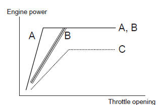
Engine power characteristics can be changed in 3 modes by operating the drive mode selector to meet various riding conditions and rider’s preference.
Operation
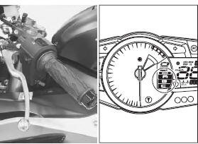
Drive mode is preset at a-mode when the ignition switch and engine stop switch are turned on. Follow the procedure below to operate drive mode selector.
- Turn on the ignition switch and engine stop switch.
- Push the drive mode selector up
 or down
 for 1 second until the drive
mode indicator shows a. - Push the drive mode selector to change drive mode.
Pushing the up
 switch can
change from a to c to b to a. Pushing the down
switch can change from a to b to c to a. The drive mode indicator indicates actual drive mode.
Note
|
Drive mode
A-mode
A-mode provides sharp throttle response at all throttle opening range to obtain maximum engine power.
B-mode
B-mode provides softer throttle response than a-mode up to middle throttle opening range.
C-mode
C-mode provides soft throttle response at all throttle opening range by reducing engine power.
 Immobilizer description (for e-02, 19, 24, 51)
The immobilizer, an anti-theft system, is installed as a
standard equipment.
The immobilizer verifies that the key id agrees with ecm
id by means of radio communication through the
immobilizer a ...
 Schematic and routing diagram
Ignition system diagram
Refer to “wire color symbols” in section 0a .
Ignition system components location
Refer to “electrical components location” in section 0a . ...
Other materials:
Cushion rod removal and installation
Removal
Remove the right side cowling and side frame covers. Refer to “exterior
parts removal and installation” in section 9d .
Support the motorcycle with a jack to relieve load on
the cushion rod.
Remove the muffler chamber. Refer to “muffler / muffler chamber /
exhaust ...
Drive chain related components
Drive chain
Engine sprocket
Rear sprocket
Dust seal
Bearing
Retainer
Sprocket mounting drum
Wheel damper
145 N·m (14.5 Kgf-m,
105.0 Lbf-ft)
60 N·m
(6.0 Kgf-m, 43.0 Lbf-ft)
Apply grease
Apply thread lock to
thread p ...
Specifications
Service data
Suspension
unit: mm (in)
Tightening torque specifications
Note
the specified tightening torque is described in the following.
“Front fork components”
Reference: for the tightening torque of fastener not specified in this
section, refer to “tightening ...