Suzuki GSX-R 1000 Service Manual: DTC “c12” (p0335): ckp sensor circuit malfunction.
Detected condition and possible cause
|
Detected condition |
Possible cause |
| The signal does not reach ecm for 3 sec. Or more, after receiving the starter signal. |
|
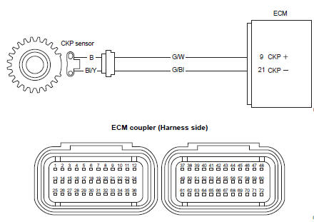
Wiring diagram
Troubleshooting
| Caution when using the multi-circuit tester, do not strongly touch the terminal of the ecm coupler with a needle pointed tester probe to prevent terminal damage. |
| Note after repairing the trouble, clear the dtc using sds tool. Refer to “use of sds diagnosis reset procedures” . |
|
Step |
Action |
Yes |
No |
|
1 |
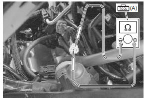
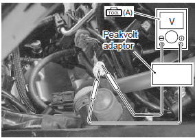
Special tool (a): 09900–25008 (multi circuit tester set) Tester knob indication resistance (Ω) Ckp sensor resistance 142 – 194 Ω (b – bl/y)
Special tool
Ckp sensor continuity ∞Ω¶ (infinity) (b . Ground, bl/y. Ground)
Are the resistance and continuity ok? |
Go to step 2. | Replace the ckp sensor with a new one. |
|
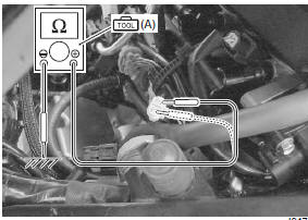
2 |
Special tool
Tester knob indication
voltage ( Ckp sensor peak voltage 0.5 V and more ((+) terminal: b – (–) terminal: bl/y)
Is the voltage ok? |
|
|
 (a): 09900–25008 (multi
 (a): 09900–25008 (multi
 )
)
 DTC “c11” (p0340): cmp sensor circuit
malfunction
DTC “c11” (p0340): cmp sensor circuit
malfunction
Detected condition and possible cause
Detected condition
Possible cause
The signal does not reach ecm for 3 sec. Or more, after
receiving the starter signal.
...
 DTC “c13” (p0105-h/l): iap sensor circuit
malfunction
DTC “c13” (p0105-h/l): iap sensor circuit
malfunction
Detected condition and possible cause
Detected condition
Possible cause
C13
Iap sensor voltage is not within the
following range.
0.5 V ≤ Sensor voltage &l ...
Other materials:
Country and area codes
The following codes stand for the applicable country(-ies) and area(-s).
Wire color symbols
Warning, caution and information labels location
Noise label
Information label
Vacuum hose routing label
Fuel information label
Manual notice label
Screen la ...
Rear brake light switch inspection and adjustment
Check the rear brake light switch so that the brake light
will come on just before pressure is felt when the brake
pedal is depressed. If the brake light switch adjustment
is necessary, turn the adjuster nut (1) in or out while
holding the brake pedal.
Brake fluid level check
Refer to “bra ...
Excv cable removal and installation
Removal
Turn the ignition switch off.
Remove the front seat. Refer to “exterior parts
removal and installation” in section 9d (page 9d-
6).
Remove the left side cowling. Refer to “exterior parts removal and
installation” in section 9d .
Connect the special tool (mo ...