Suzuki GSX-R 1000 Service Manual: DTC “c31” (p0705): gp switch circuit malfunction
Detected condition and possible cause
|
Detected condition |
Possible cause |
| No gear position switch voltage
Gp switch voltage is not within the following range. Gp switch voltage > 0.6 V |
|
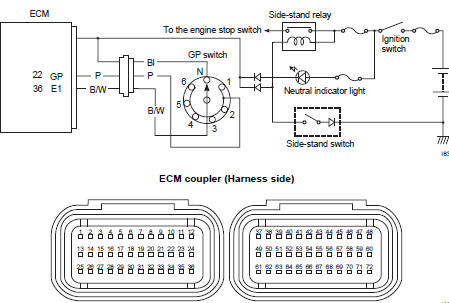
Wiring diagram
Troubleshooting
| Caution when using the multi-circuit tester, do not strongly touch the terminal of the ecm coupler with a needle pointed tester probe to prevent terminal damage. |
| Note after repairing the trouble, clear the dtc using sds tool. Refer to “use of sds diagnosis reset procedures” . |
|
Step |
Action |
Yes |
No |
|
1 |
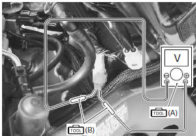
Special tool Tester knob indication voltage ( ) Gp switch voltage 0.6 V and more ((+) terminal: p – (–) terminal: b/w)
Is the voltage ok? |
|
|
 DTC “c29” (p1654-h/l): secondary throttle
position sensor (stps) circuit malfunction
DTC “c29” (p1654-h/l): secondary throttle
position sensor (stps) circuit malfunction
Detected condition and possible cause
Detected condition
Possible cause
C29
Output voltage is not within the following
range.
Difference between actual throttle op ...
 Dtc “c32” (p0201), “c33” (p0202), “c34” (p0203) or “c35” (p0204): primary
fuel injector circuit
malfunction
Dtc “c32” (p0201), “c33” (p0202), “c34” (p0203) or “c35” (p0204): primary
fuel injector circuit
malfunction
Detected condition and possible cause
Detected condition
Possible cause
Ckp signal is produced but fuel injector signal is
interrupted by 4 times or more continuity
...
Other materials:
Turn signal / side-stand relay removal and installation
Removal
Remove the frame cover. Refer to “exterior parts
removal and installation” in section 9d (page 9d-
6).
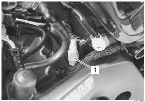
Remove the turn signal/side-stand relay (1).
Installation
Install the turn signal/side-stand relay in the reverse
order of removal. ...
Specifications
Service data
Oil pump
Oil
Tightening torque specifications
Reference: for the tightening torque of fastener not specified in this
section, refer to “tightening torque list” in section 0c . ...
Warning / caution / note
Please read this manual and follow its instructions
carefully. To emphasize special information, the symbol
and the words warning, caution and note have
special meanings. Pay special attention to the messages
highlighted by these signal words.
Indicates a
potential hazard that could ...