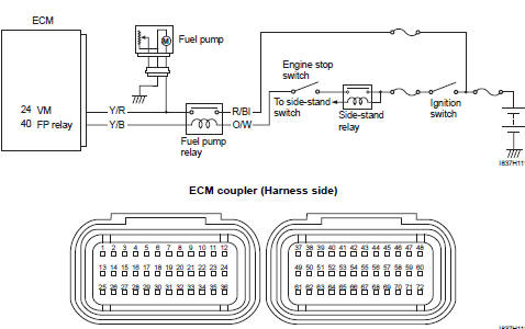
Suzuki GSX-R 1000 Service Manual: DTC “c41” (p0230-h/l): fp relay circuit malfunction
Detected condition and possible cause
|
Detected condition |
Possible cause |
||
|
C41 |
No voltage is applied to fuel pump. |
|
|
|
P0230 |
H |
Voltage is applied to fuel pump although fuel pump relay is turned off. | |
|
L |
No voltage is applied to fuel pump although fuel pump relay is turned on. | ||
Wiring diagram
Troubleshooting
| Caution when using the multi-circuit tester, do not strongly touch the terminal of the ecm coupler with a needle pointed tester probe to prevent terminal damage. |
| Note after repairing the trouble, clear the dtc using sds tool. Refer to “use of sds diagnosis reset procedures” . |
C41 (use of mode select switch)
|
Step |
Action |
Yes |
No |
|
1 |
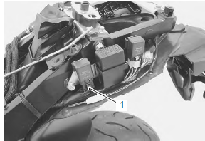
Is the fp relay ok? |
|
Replace the fp relay with a new one. |
P0230-h (use of sds)
|
Step |
Action |
Yes |
No |
|
1 |
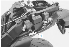
Is the fp relay ok? |
|
Replace the fp relay with a new one. |
P0230-l (use of sds)
|
Step |
Action |
Yes |
No |
|
1 |
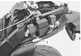
Is the fp relay ok? |
|
Replace the fp relay with a new one. |
 DTC “c40” (p0505 / p0506 / p0507): isc
valve circuit malfunction
DTC “c40” (p0505 / p0506 / p0507): isc
valve circuit malfunction
Detected condition and possible cause
Detected condition
Possible cause
C40/P0505
The circuit voltage of motor drive is
unusual.
Isc valve circuit open or ...
 DTC “c41” (p2505): ecm power input signal
malfunction
DTC “c41” (p2505): ecm power input signal
malfunction
Detected condition and possible cause
Detected condition
Possible cause
C41/P2505
No voltage is applied to the ecm.
Lead wire/coupler connection of ecm t ...
Other materials:
Battery removal and installation
Removal
Remove the front seat. Refer to “exterior parts
removal and installation” in section 9d (page 9d-
6).
Disconnect the battery (–) lead wire (1).
Disconnect the battery (+) lead wire (2).
Note
be sure to disconnect the battery (–) lead
wire (1) first, th ...
Engine stop switch inspection
Inspect the engine stop switch in the following
procedures:
turn the ignition switch off.
Remove the air cleaner box. Refer to “air cleaner box removal and
installation” in section 1d .
Disconnect the right handlebar switch coupler (1).
Inspect the engine stop ...
Washing the motorcycle
When washing the motorcycle,
follow the instructions below:
Remove dirt and mud from the
motorcycle with running water.
You may use a soft sponge or
brush. Do not use hard materials
which can scratch the
paint.
Wash the entire motorcycle
with a mild detergent or car
...