Suzuki GSX-R 1000 Service Manual: DTC “c91” (p0500): vehicle speed sensor circuit malfunction
Detected condition and possible cause
|
Detected condition |
Possible cause |
| Speedometer does not receive signal from the vehicle speed sensor for more than 6 sec. When the motorcycle is running. Ecm does not receive signal from the vehicle speed sensor for more than 6 sec. When the motorcycle is running. Failure in communication between ecm and speedometer with reference to vehicle speed. |
|
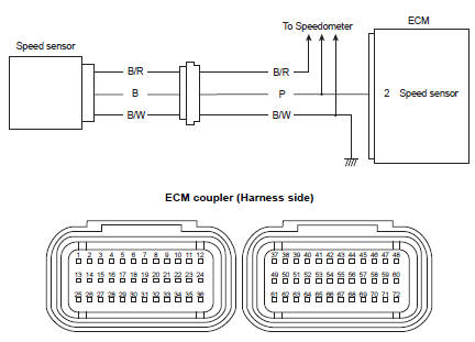
Wiring diagram
Troubleshooting
| Caution when using the multi-circuit tester, do not strongly touch the terminal of the ecm coupler with a needle pointed tester probe to prevent terminal damage. |
| Note after repairing the trouble, clear the dtc using sds tool. Refer to “use of sds diagnosis reset procedures” . |
|
Step |
Action |
Yes |
No |
|
|
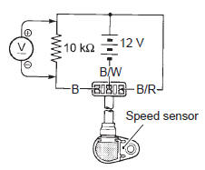
1 |
Special tool Tester knob indication
voltage (
Is the voltage ok? |
|
|
 (a): 09900–25008 (multi
 )
)
 DTC “c62” (p0443): evap system purge
control solenoid valve circuit malfunction
(e-33 only)
DTC “c62” (p0443): evap system purge
control solenoid valve circuit malfunction
(e-33 only)
Detected condition and possible cause
Detected condition
Possible cause
Evap system purge control valve voltage is not input to
ecm.
Evap system purge contro ...
 DTC “c93” (p1769): steering damper
solenoid valve circuit malfunction
DTC “c93” (p1769): steering damper
solenoid valve circuit malfunction
Detected condition and possible cause
Detected condition
Possible cause
C93
Steering damper control current does not flow to
the solenoid valve. With ig turned on ...
Other materials:
Be extra safety-conscious on bad weather days
Riding on bad weather days,
especially wet ones, requires
extra caution. Braking distances
increase on a rainy day. Stay off
the painted surface marks, manhole
covers, and greasy-appearing
areas, as they can be
especially slippery. Use extra caution
at railway crossings and on
metal grating ...
Tp sensor adjustment
Inspect the tp sensor setting position and adjust it if
necessary in the following procedures:
connect the special tool (mode select switch) to the dealer mode
coupler. Refer to “self-diagnostic procedures” in section 1a .
Special tool
: 09930–82720 (mode selection switch)
Warn ...
Isc valve reset
When removing or replacing the throttle body assembly,
reset the isc valve learned value in the following
procedures:
turn the ignition switch on position.
Set up the sds tools. (Refer to the sds operation
manual for further details.)
Click “active control”.
Click “is ...