Suzuki GSX-R 1000 Service Manual: Electrical parts connector / coupler
- Faulty fi system is often related to poor electrical contact of connector/coupler. Before servicing individual electronic part, check electrical contact of the connector/coupler.
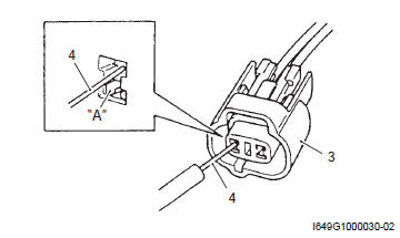
- When connecting a connector, be sure to push it in until a click is felt.
- With a lock type coupler, be sure to release the lock when disconnecting, and push it in fully to engage the lock when connecting.
- When disconnecting the coupler, be sure to hold the coupler body and do not pull the lead wires.
- Inspect each terminal on the connector/coupler for looseness or bending.
- Push in the coupler straightly. An angled or skewed insertion may cause the terminal to be deformed, possibly resulting in poor electrical contact.
- Inspect each terminal for corrosion and contamination. The terminals must be clean and free of any foreign material which could impede proper terminal contact.
- Before refitting the sealed coupler, make sure its seal rubber is positioned properly. The seal rubber may possibly come off the position during disconnecting work and if the coupler is refitted with the seal rubber improperly positioned, it may result in poor water sealing.
- Inspect each lead wire circuit for poor connection by shaking it by hand lightly. If any abnormal condition is found, repair or replace.
When taking measurements at electrical connectors using a tester probe, be sure to insert the probe from the wire harness side (rear) of the connector/coupler.
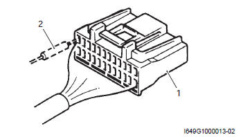
- Coupler
- Probe
- When connecting meter probe from the terminal side of the coupler (where connection from harness side not being possible), use extra care not to force and cause the male terminal to bend or the female terminal to open. Connect the probe as shown to avoid opening of female terminal. Never push in the probe where male terminal is supposed to fit.
- Check the male connector for bend and female connector for excessive opening. Also check the coupler for locking (looseness), corrosion, dust, etc.
- Coupler
- Probe
- Where male terminal fits
- Avoid applying grease or other similar material to connector/coupler terminals to prevent electric trouble.
 Precautions for electrical circuit service
When handling the electrical parts or servicing fi
system, observe the following points for the safety of the
systems. ...
 Clamp
Clamp
Clamp the wire harness at such positions as indicated in “wiring harness
routing diagram” in section 9a .
Bend the clamp properly so that the wire harness is
clamped securely.
...
Other materials:
Evaporative emission control system
removal and installation (only for e-33)
Hose
removal
Lift and support the fuel tank. Refer to “fuel tank
removal and installation” in section 1g (page 1g-
9).
Remove the frame cover assembly. Refer to “exterior parts removal and
installation” in section 9d .
Remove the evap hoses as shown in the evap canister h ...
Regulated voltage inspection
Inspect the regulated voltage in the following
procedures:
remove the front seat. Refer to “exterior parts
removal and installation” in section 9d (page 9d-
6).
Start the engine and keep it running at 5 000 r/min
with the dimmer switch turned hi position.
Measure the dc vo ...
Stp sensor adjustment
Adjust the stp sensor in the following procedures:
remove the air cleaner box cover. Refer to “air cleaner element removal
and installation” in section 1d .
Disconnect the stva lead wire coupler (1).
Insert the needle pointed probes to the stp sensor
coupler (between y/w a ...