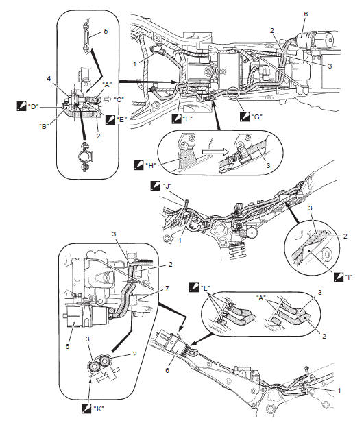
Suzuki GSX-R 1000 Service Manual: Evap canister hose routing diagram (only for e-33)
|
 Face the
 Face the
 Pass the
 Pass the
 Stick the
 Pass the
 Face the
 Face the
 Face the
 Pair system hose routing diagram
Pair control solenoid valve
Pair reed valve
White marking (hidden side)
Yellow marking
Blue marking
Red marking
Face the
clamp end to the top.
Mak ...

Other materials:
Rear brake caliper disassembly and
assembly
Refer to “rear brake caliper removal and installation” .
Disassembly
Remove the pad spring (1) and rubber boot (2) from
the caliper.
Place a rag over the piston to prevent it from popping
out and then force out the piston using compressed
air.
Caution
do not use hig ...
Maintenance schedule
It is very important to inspect and
maintain your motorcycle regularly.
Follow the guidelines in the
chart. The intervals between periodic
services in kilometers, miles
and months are shown. At the
end of each interval, be sure to
perlorm the maintenance listed.
Warning
Improper ...
Break-in
The first 800 km (500 miles) is the
most important in the life of your
motorcycle. Proper operation during
this break-in period will help
assure maximum life and performance
from your new motorcycle.
The following guidelines explain
proper break-in procedures.
Maximum engine speed recommen ...