Suzuki GSX-R 1000 Service Manual: Excv cable removal and installation
Removal
- Turn the ignition switch off.
- Remove the front seat. Refer to “exterior parts removal and installation” in section 9d (page 9d- 6).
- Remove the left side cowling. Refer to “exterior parts removal and installation” in section 9d .
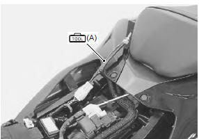
- Connect the special tool (mode select switch) to the dealer mode coupler. Refer to “self-diagnostic procedures” in section 1a .
- After turning the mode select switch on, turn the ignition switch on.
Special tool
 (a): 09930–82720 (mode selection
switch)
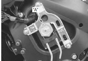
- Check that the cable slots of the excva pulley comes to the middle (adjustment position) “a”.
- Turn the ignition switch off.
| Caution before removing the excv cables, be sure to set the excva pulley to the adjustment position. |
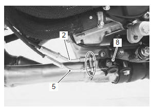
- Loosen the lock-nut (1) on the no. 2 Cable (2) and turn in the cable adjuster (3) fully.
- Loosen the lock-nut (4) on the no. 1 Cable (5) and turn in the cable adjuster (6) fully.
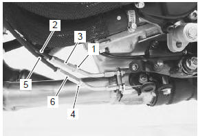
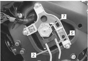
- Disconnect the no. 2 Cable (2) and no. 1 Cable (5) from the excva pulley (7).
- Loosen the lock-nuts.
- Disconnect the no. 2 Cable (2) and no. 1 Cable (5) from the excv pulley (8).
Installation
| Caution the cable slots of excva pulley must be located adjustment position. |
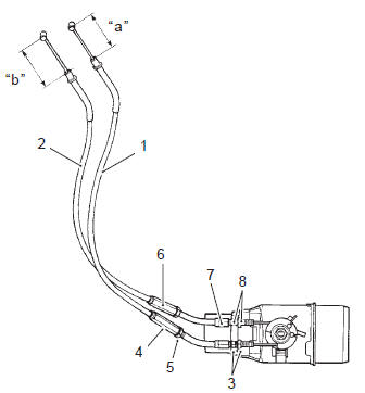
- Temporarily connect the excv cable no. 1 (47H0cl) (1) and no. 2 (47H0op) (2) to the exhaust pipe and excv pulley.
| Note the excv cables are identified by the letters. No. 1 Cable (1): 47h0cl no. 2 Cable (2): 47h0op |
- Tighten the lock-nuts (3) on the no. 1 Cable.
- Adjust the inner cable length “a” of no. 1 Cable in 42 – 43 mm (1.65 – 1.69 In) by turning the adjuster (4), then tighten the lock-nuts (5).
- Turn in the adjuster (6) on the no. 2 Cable fully.
- Turn the no. 2 Cable adjuster (7) in or out until the
inner cable length “b” becomes 60 – 61 mm (2.36 –
2.40 In).
After adjusting the inner cable length “b”, tighten the lock-nuts (8).
- Connect the other end of excv cable no. 1 (1) And no. 2 (2) To the excva pulley (9).
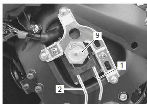
- After connecting the no. 2 Cable (2), loosen the locknut (10) and turn the adjuster (6) in or out until 11 – 12 mm (0.43 – 0.47 In) of the thread length “c” on the cable adjuster can be provided and tighten the locknut (10).
- Inspect the excva position sensor output voltage.
Refer to “excva adjustment” .
 Exhaust system components
Exhaust pipe gasket
Exhaust pipe assembly
Ho2 sensor
Connector
: install the connector so that the
chamfer side faces backward.
Muffler chamber
Muffler ...
 Excva removal and installation
Removal
Turn the ignition switch off.
Remove the left side cowling. Refer to “exterior parts removal and
installation” in section 9d .
Connect the special tool (mode select swit ...
Other materials:
Crankcase breather (pcv) cover inspection
Inspect the crankcase breather (pcv) cover in the
following procedures:
remove the crankcase breather (pcv) cover. Refer to “crankcase breather
(pcv) hose / reed valve / cover removal and installation” .
Inspect the crankcase breather (pcv) cover for
carbon deposit. If carbon ...
Specifications
Tightening torque specifications
Note
the specified tightening torque is described in the following.
“Chassis bolt and nut inspection”
Reference: for the tightening torque of fastener not specified in this
section, refer to “tightening torque list” in section 0c . ...
Clutch parts inspection
Refer to “clutch removal” and “clutch installation” .
Clutch drive and driven plate
Note
wipe off the engine oil from the drive and
driven plates with a clean rag.
Measure the thickness of drive plates with a vernier
calipers. If the drive plate thickness is found to have ...