Suzuki GSX-R 1000 Service Manual: Excva adjustment
Inspect the excva operation and adjust it if necessary in the following steps:
Step 1
- Set the excva to the adjustment position. Refer to “excv cable removal and installation” (page 1k- 6).
Step 2
- Turn the ignition switch off.
- Turn the mode select switch off.
- Turn the ignition switch on and check the operation
of excva.
(Excva operation order: full close → full open → approx. 60% Open)
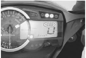
- Turn the mode select switch on. If dtc “c46” is not indicated on the lcd display, the adjustment is correctly completed. If “c46” is indicated, repeat the procedures from step 3 to step 4.
Step 3
- Turn the ignition switch off.
- Set up the sds tools. Refer to “self-diagnostic procedures” in section 1a .
- Turn the ignition switch on.
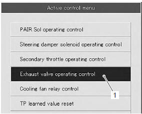
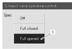
- Click “exhaust valve operating control” (1).
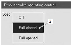
- Click “full closed” (2).
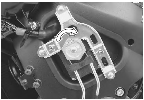
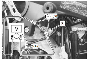
- Insert the needle pointed probes into the back side of the excva coupler (3). ((+) Y – (–) w)
- Measure the excva position sensor output voltage at excv fully closed position.
Special tool
 (a): 09900–25008 (multi circuit
tester set)
 (b): 09900–25009 (needle-point
probe set)
Tester knob indication
voltage ( )
)
Excva position sensor output voltage excv is fully closed: 0.45 ≤ Output voltage ≤ 1.4 V ((+) y - (-) W)
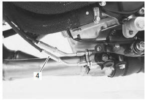
- If the measured voltage is less than specification, adjust the no. 1 Cable adjuster (4) as follows:
- set the excva to the adjustment position. Refer to “excv cable removal and installation” .
| Caution adjusting the no. 1 Cable with the excv fully closed can damage the excva. Be sure to adjust the no. 1 Cable with the excv set in the adjustment position. |
- Turn the no. 1 Cable adjuster (4) in or out to set the output voltage within the specified value.
| Note if c46 code is indicated after adjusting the voltage, increase the voltage to 0.9 V. |
Step 4
- Measure the excva position sensor output voltage at excv fully opened position.
Special tool
 (a): 09900–25008 (multi circuit
tester set)
 (b): 09900–25009 (needle-point
probe set)
Excva position sensor out put voltage excv is fully opened: 3.6 ≤ Output voltage ≤ 4.55 V ((+) y - (-) W)
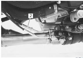
- If the measured voltage is more than specification, adjust the no. 2 Cable adjuster (2) as follows:
- set the excva to the adjustment position. Refer to “excv cable removal and installation” .
| Caution adjusting the no. 2 Cable with the excv fully opened can damage the excva. Be sure to adjust the no. 2 Cable with the excv set in adjustment position. |
- Turn out the no. 2 Cable adjuster (2) in or out to set the output voltage within the specified value.
- After adjusting the excv cables, perform step 2 to confirm dtc “46” is not indicated.
 Excva pulley inspection
Inspect the excva pulley in the following procedures:
remove the excva pulley. Refer to “excv cable removal and installation”
.
Visually inspect the excva pulley for wear and
da ...
 Muffler / muffler chamber / exhaust pipe
removal and installation
Muffler / muffler chamber / exhaust pipe
removal and installation
Removal
Loosen the muffler connecting bolts (1).
Remove the mufflers (2) by removing the mounting
bolt and nut (3).
Note
support the muffler to prevent it from falling.
...
Other materials:
Front brake caliper removal and installation
Note
the right and left calipers are installed
symmetrically and therefore the removal
procedure for one side is the same as that for
the other side.
Removal
Drain brake fluid. Refer to “brake fluid replacement” in section 4a .
Remove the brake hose from the cali ...
Precautions
Precautions for clutch system
Refer to “general precautions” in section 00 (page 00-1).
Schematic and routing diagram
Clutch cable routing diagram
Refer to “throttle cable routing diagram” in section 1d .
Diagnostic information and procedures
Clutch system symptom diagnosis
...
Headlight removal and installation
Removal
Remove the body cowling assembly. Refer to “exterior parts removal and
installation” in section 9d .
Remove the air intake pipes (1). Refer to “exterior parts removal and
installation” in section 9d .
Remove the wiring harness no. 2 (2) By
disconnecting the couplers and ...