Suzuki GSX-R 1000 Service Manual: Front brake master cylinder assembly removal and installation
Removal
- Drain brake fluid. Refer to “brake fluid replacement” .
- Disconnect the front brake light switch coupler (1).
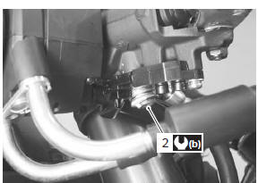
- Place a rag underneath the brake hose union bolt (2) on the master cylinder to catch any spilt brake fluid.
- Remove the brake hose union bolt (2).
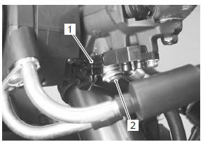
- Remove the master cylinder assembly.
Installation
Install the front brake master cylinder in the reverse order of removal. Pay attention to the following points:
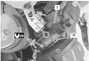
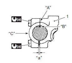
- when installing the master cylinder (1) onto the handlebar, align the master cylinder holder’s mating surface “a” with the punch mark “b” on the handlebar and tighten the upper holder bolt first.
Tightening torque front brake master cylinder holder bolt (upper and lower) (a): 10 n·m (1.0 Kgf-m, 7.0 Lbf-ft)
|
- After setting the brake hose union to the stopper, tighten the union bolt (2) to the specified torque.
| Caution the seal washers should be replaced with the new ones to prevent fluid leakage. |
Tightening torque brake hose union bolt (b): 23 n·m (2.3 Kgf-m, 16.5 Lbf-ft)
- Bleed air from the master cylinder in the same manner as caliper side.
| Note if air is trapped in the master cylinder, bleed air from the master cylinder first. |
Tightening torque air bleeder valve (front master cylinder): 6 n·m ( 0.6 Kgf-m, 4.5 Lbf-ft)
- Bleed air from brake system. Refer to “air bleeding from brake fluid circuit” .
 Front brake master cylinder components
Reservoir cap
Plate
Diaphragm
Reservoir tank
Master cylinder
Dust boot
Piston set
Brake lever
Brake lever pivot bolt
Brake lever pivot bolt lock ...
 Front brake master cylinder / brake lever disassembly and assembly
Refer to “front brake master cylinder assembly removal and installation” .
Disassembly
Remove the reservoir cap (1), plate (2), diaphragm
(3) and reservoir tank (4).
Remove the brake ...
Other materials:
Battery
Battery connection in reverse polarity is strictly
prohibited. Such a wrong connection will damage the
components of the fi system instantly when reverse
power is applied.
Removing any battery terminal of a running engine is
strictly prohibited. The moment such removal is made,
...
Rear wheel dust seal / bearing removal and installation
Removal
Remove the rear wheel assembly. Refer to “rear wheel assembly removal
and installation” .
Remove the rear sprocket mounting drum assembly
(1) from the rear wheel.
Remove the wheel dampers (2).
Remove the dust seal.
Special tool
(a): 09913–50121 (oil s ...
Diagnostic information and procedures
Engine mechanical symptom diagnosis
Refer to “engine symptom diagnosis” in section 1a .
Compression pressure check
The compression pressure reading of a cylinder is a
good indicator of its internal condition.
The decision to overhaul the cylinder is often based on
the results of a compressio ...