Suzuki GSX-R 1000 Service Manual: Self-diagnostic procedures
Use of mode select switch
Note
|
- Remove the front seat. Refer to “exterior parts removal and installation” in section 9d (page 9d- 6).
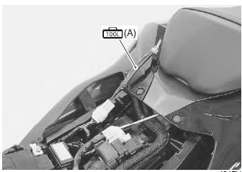
- Connect the special tool to the mode select switch coupler.
Special tool
 (a): 09930–82720 (mode selection
switch)
- Start the engine or crank the engine for more than 4 seconds.
- Turn the special tool’s switch on.
- Check the dtc to determine the malfunction part.
Refer to “dtc table” .
Special tool
(a): 09930–82720 (mode selection
switch)
- After repairing the trouble, turn off the ignition switch and turn on again. If dtc is indicated (c00), the malfunction is cleared.
Note
|
- Turn the ignition switch off and disconnect the special tool from the mode select switch coupler.
- Reinstall the front seat.
Use of sds
Note
|
- Remove the front seat. Refer to “exterior parts removal and installation” in section 9d (page 9d- 6).
- Set up the sds tools. (Refer to the sds operation manual for further details.)
Special tool
 (a): 09904–41010 (suzuki diagnostic
system set)
 (b): 99565–01010–020 (cd-rom
ver.20)
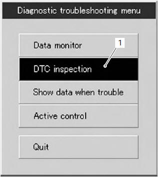
- Click the dtc inspection button (1).
- Start the engine or crank the engine for more than 4 seconds.
- Check the dtc to determine the malfunction part.
Refer to “dtc table” .
Note
|
- After repairing the trouble, clear to delete history code (past dtc). Refer to “use of sds diagnosis reset procedures” .
- Close the sds tool and turn the ignition switch off.
- Disconnect the sds tool and install the front seat.

 Use of sds diagnosis reset procedures
Note
the malfunction code is memorized in the
ecm also when the lead wire coupler of any
sensor is disconnected. Therefore, when a
lead wire coupler has been disconnected at
the ...
Other materials:
Fi system troubleshooting
Customer complaint analysis
Record details of the problem (failure, complaint) and how it occurred as
described by the customer. For this purpose,
use of such an inspection form such as following will facilitate collecting
information to the point required for proper
analysis and diagnosis.
...
Engine oil level check
Check the engine oil level as follows:
Place the motorcycle on level
ground on the side stand.
Start the engine and allow it to
idle for a few minutes.
Stop the engine and wait three
minutes.
Hold the motorcycle vertically
and check the oil level through
...
Turn signal / side-stand relay removal and installation
Removal
Remove the frame cover. Refer to “exterior parts
removal and installation” in section 9d (page 9d-
6).
Remove the turn signal/side-stand relay (1).
Installation
Install the turn signal/side-stand relay in the reverse
order of removal. ...