Suzuki GSX-R 1000 Service Manual: Excva adjustment
Inspect the excva operation and adjust it if necessary in the following steps:
Step 1
- Set the excva to the adjustment position. Refer to “excv cable removal and installation” (page 1k- 6).
Step 2
- Turn the ignition switch off.
- Turn the mode select switch off.
- Turn the ignition switch on and check the operation
of excva.
(Excva operation order: full close → full open → approx. 60% Open)
- Turn the mode select switch on. If dtc “c46” is not indicated on the lcd display, the adjustment is correctly completed. If “c46” is indicated, repeat the procedures from step 3 to step 4.
Step 3
- Turn the ignition switch off.
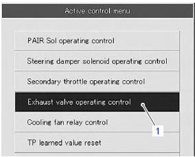
- Set up the sds tools. Refer to “self-diagnostic procedures” in section 1a .
- Turn the ignition switch on.
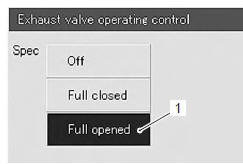
- Click “exhaust valve operating control” (1).
- Click “full closed” (2).
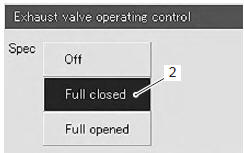
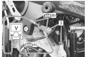
- Insert the needle pointed probes into the back side of the excva coupler (3). ((+) Y – (–) w)
- Measure the excva position sensor output voltage at excv fully closed position.
Special tool
 (a): 09900–25008 (multi circuit
tester set)
 (b): 09900–25009 (needle-point
probe set)
Tester knob indication
voltage ( )
)
Excva position sensor output voltage excv is fully closed: 0.45 ≤ Output voltage ≤ 1.4 V ((+) y - (-) W)
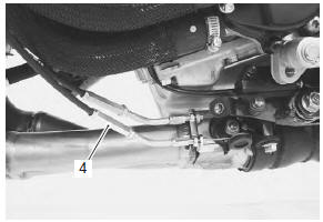
- If the measured voltage is less than specification, adjust the no. 1 Cable adjuster (4) as follows:
- set the excva to the adjustment position. Refer to “excv cable removal and installation” .
| Caution adjusting the no. 1 Cable with the excv fully closed can damage the excva. Be sure to adjust the no. 1 Cable with the excv set in the adjustment position. |
- Turn the no. 1 Cable adjuster (4) in or out to set the output voltage within the specified value.
| Note if c46 code is indicated after adjusting the voltage, increase the voltage to 0.9 V. |
Step 4
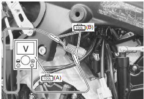
- Measure the excva position sensor output voltage at excv fully opened position.
Special tool
 (a): 09900–25008 (multi circuit
tester set)
 (b): 09900–25009 (needle-point
probe set)
Excva position sensor out put voltage excv is fully opened: 3.6 ≤ Output voltage ≤ 4.55 V ((+) y - (-) W)
- If the measured voltage is more than specification, adjust the no. 2 Cable adjuster (2) as follows:
- set the excva to the adjustment position. Refer to “excv cable removal and installation” .
| Caution adjusting the no. 2 Cable with the excv fully opened can damage the excva. Be sure to adjust the no. 2 Cable with the excv set in adjustment position. |
- Turn out the no. 2 Cable adjuster (2) in or out to set the output voltage within the specified value.
- After adjusting the excv cables, perform step 2 to confirm dtc “46” is not indicated.
 Excva pulley inspection
Inspect the excva pulley in the following procedures:
remove the excva pulley. Refer to “excv cable removal and installation”
.
Visually inspect the excva pulley for wear and
da ...
 Muffler / muffler chamber / exhaust pipe
removal and installation
Muffler / muffler chamber / exhaust pipe
removal and installation
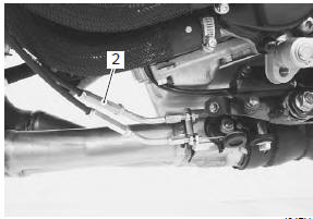
Removal
Loosen the muffler connecting bolts (1).
Remove the mufflers (2) by removing the mounting
bolt and nut (3).
Note
support the muffler to prevent it from falling.
...
Other materials:
Starter relay removal and installation
Removal
Turn the ignition switch off.
Remove the front seat. Refer to “exterior parts
removal and installation” in section 9d (page 9d-
6).
Disconnect the battery (–) lead wire (1) from the
battery.
Remove the starter relay cover (2) and disconnect
the starter rel ...
Exhaust pipe bolt and muffler bolt inspection
Tighten exhaust pipe bolts and muffler bolts
initially at 1 000 km (600 miles, 2 months) and every
12 000 km (7 500 miles, 24 months) thereafter
Check the exhaust pipe bolts and muffler bolts to the
specified torque.
Tightening torque
exhaust pipe bolt (a): 23 n·m (2.3 Kgf-m, 16.5 Lbf-ft)
muf ...
Fuel level gauge inspection
Inspect the fuel level gauge in the following procedures:
remove the fuel pump. Refer to “fuel pump disassembly and assembly” in
section 1g .
Measure the resistance at each fuel level gauge in
float position. If the resistance is incorrect, replace
fuel level gauge with a ne ...