Suzuki GSX-R 1000 Service Manual: DTC “c41” (p0230-h/l): fp relay circuit malfunction
Detected condition and possible cause
|
Detected condition |
Possible cause |
||
|
C41 |
No voltage is applied to fuel pump. |
|
|
|
P0230 |
H |
Voltage is applied to fuel pump although fuel pump relay is turned off. | |
|
L |
No voltage is applied to fuel pump although fuel pump relay is turned on. | ||
Wiring diagram
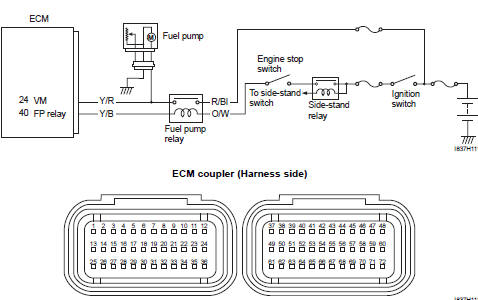
Troubleshooting
| Caution when using the multi-circuit tester, do not strongly touch the terminal of the ecm coupler with a needle pointed tester probe to prevent terminal damage. |
| Note after repairing the trouble, clear the dtc using sds tool. Refer to “use of sds diagnosis reset procedures” . |
C41 (use of mode select switch)
|
Step |
Action |
Yes |
No |
|
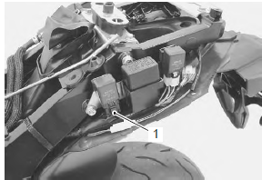
1 |
Is the fp relay ok? |
|
Replace the fp relay with a new one. |
P0230-h (use of sds)
|
Step |
Action |
Yes |
No |
|
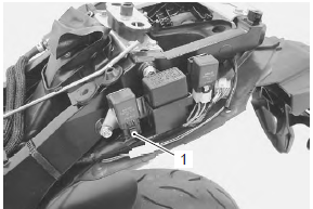
1 |
Is the fp relay ok? |
|
Replace the fp relay with a new one. |
P0230-l (use of sds)
|
Step |
Action |
Yes |
No |
|
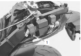
1 |
Is the fp relay ok? |
|
Replace the fp relay with a new one. |
 DTC “c40” (p0505 / p0506 / p0507): isc
valve circuit malfunction
DTC “c40” (p0505 / p0506 / p0507): isc
valve circuit malfunction
Detected condition and possible cause
Detected condition
Possible cause
C40/P0505
The circuit voltage of motor drive is
unusual.
Isc valve circuit open or ...
 DTC “c41” (p2505): ecm power input signal
malfunction
DTC “c41” (p2505): ecm power input signal
malfunction
Detected condition and possible cause
Detected condition
Possible cause
C41/P2505
No voltage is applied to the ecm.
Lead wire/coupler connection of ecm t ...
Other materials:
Immobilizer description (for e-02, 19, 24, 51)
The immobilizer, an anti-theft system, is installed as a
standard equipment.
The immobilizer verifies that the key id agrees with ecm
id by means of radio communication through the
immobilizer antenna. When the id agreement is verified,
the system makes the engine ready to start.
...
Swingarm bearing removal and installation
Removal
Remove the swingarm. Refer to “swingarm removal and installation” .
Remove the swingarm pivot bearings (1) using the
special tool.
Special tool
(a):
09921–20240 (bearing remover set)
Remove the center spacer (2).
Remove the cushion lever bearing (3) usin ...
Front wheel assembly removal and installation
Removal
Remove the brake calipers, left and right.
Caution
do not operate the brake lever with the
caliper removed.
Loosen two axle pinch bolts (1) on the right front fork
leg.
Remove the front axle bolt (2).
Raise the front wheel off the ground a ...