Suzuki GSX-R 1000 Service Manual: DTC “c41” (p2505): ecm power input signal malfunction
Detected condition and possible cause
|
Detected condition |
Possible cause |
|
|
C41/P2505 |
No voltage is applied to the ecm. |
|
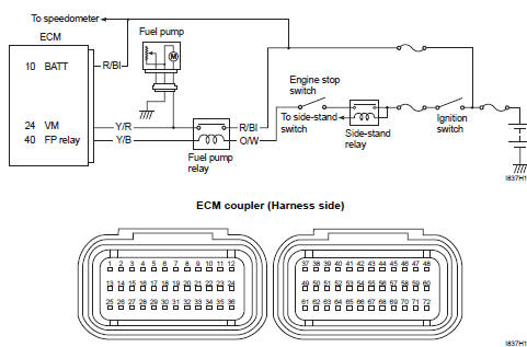
Wiring diagram
Troubleshooting
| Caution when using the multi-circuit tester, do not strongly touch the terminal of the ecm coupler with a needle pointed tester probe to prevent terminal damage. |
| Note after repairing the trouble, clear the dtc using sds tool. Refer to “use of sds diagnosis reset procedures” . |
|
Step |
Action |
Yes |
No |
|
1 |
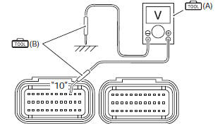
Special tool Tester knob indication voltage ( ) Ecm input voltage battery voltage ((+) terminal: “10” – (–) terminal: ground) Ecm couplers (harness side)
Is the voltage ok? |
|
Open or short circuit in the r/bl wire. |
 DTC “c41” (p0230-h/l): fp relay circuit
malfunction
DTC “c41” (p0230-h/l): fp relay circuit
malfunction
Detected condition and possible cause
Detected condition
Possible cause
C41
No voltage is applied to fuel pump.
Fuel pump relay circuit open or short.
...
 DTC “c42” (p1650): ig switch circuit
malfunction
DTC “c42” (p1650): ig switch circuit
malfunction
Detected condition and possible cause
Detected condition
Possible cause
Ignition switch signal is not input to the ecm.
Ignition system circuit open or short.
...
Other materials:
Drive mode selector inspection
Inspect the drive mode selector in the following procedures:
set up the sds tool. (Refer to the sds operation manual for
further details.)
Turn the ignition switch on.
Click “data monitor”.
Make sure each of “driving mode selection” on the monitor is
indicated ...
Rear wheel related parts inspection
Refer to “rear wheel assembly removal and installation” .
Tire
Refer to “tire inspection” in section 0b .
Rear brake disc
Refer to “rear brake disc inspection” in section 4c .
Wheel damper
Refer to “drive chain related parts inspection” in section 3a .
Sprocket
Refer to “drive chain ...
Turn signal / side-stand relay removal and
installation
Removal
Turn the ignition switch off.
Remove the frame cover assembly. Refer to “exterior parts removal and
installation” in section 9d .
Remove the turn signal/side-stand relay (1).
Installation
Install the turn signal/side-stand relay in the reverse
order of removal ...