Suzuki GSX-R 1000 Service Manual: Brake fluid replacement
| Caution handle brake fluid with care: the fluid reacts chemically with paint, plastic, rubber materials, etc. |
Front brake
- Place the motorcycle on a level surface and keep the handlebars straight.
- Remove the brake fluid reservoir cap and diaphragm.
- Suck up the old brake fluid as much as possible.
- Fill the reservoir with new brake fluid.
Bf: brake fluid (dot 4)
- Connect a clear hose to the air bleeder valve and insert the other end of the hose into a receptacle.
- Loosen the air bleeder valve and pump the brake lever until the old brake fluid flows out of the brake system.
- Close the air bleeder valve and disconnect the clear hose.
Tightening torque air bleeder valve (front caliper): 7.5 N·m (0.75 Kgf-m, 5.5 Lbf-ft)
- Fill the reservoir with brake fluid to the upper mark of the reservoir.
- Bleed air from the brake fluid circuit. Refer to “air bleeding from brake fluid circuit” .
- Install the diaphragm and reservoir cap.
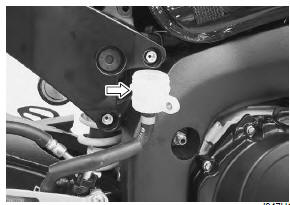
Rear brake
- Place the motorcycle on a level surface.
- Remove the right side frame cover. Refer to “exterior parts removal and installation” in section 9d .
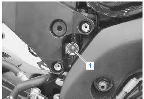
- Remove the rear brake fluid reservoir mounting bolt (1).
- Remove the brake fluid reservoir cap and diaphragm.
- Suck up the old brake fluid as much as possible.
- Fill the reservoir with new brake fluid.
Bf: brake fluid (dot 4)
- Connect a clear hose to the air bleeder valve and insert the other end of the hose into a receptacle.
- Loosen the air bleeder valve and pump the brake pedal until the old brake fluid flows out of the brake system.
- Close the air bleeder valve and disconnect the clear hose.
Tightening torque air bleeder valve (rear caliper): 6 n·m (0.6 Kgfm, 4.5 Lbf-ft)
- Fill the reservoir with brake fluid to the upper line of the reservoir.
- Bleed air from the brake fluid circuit. Refer to “air bleeding from brake fluid circuit” .
- Install the diaphragm and reservoir cap.
- Install the removed parts.
 Air bleeding from brake fluid circuit
Air trapped in the brake fluid circuit acts like a cushion to
absorb a large proportion of the pressure developed by
the master cylinder and thus interferes with the full
braking performance of the ...
 Front brake hose removal and installation
Removal
Drain brake fluid. Refer to “brake fluid replacement” .
2) Remove the front brake hoses as shown in the front brake hose routing
diagram. Refer to “front brake hose routing diagram” ...
Other materials:
Excva adjustment
Inspect the excva operation and adjust it if necessary
in the following steps:
Step 1
Set the excva to the adjustment position. Refer to
“excv cable removal and installation” (page 1k-
6).
Step 2
Turn the ignition switch off.
Turn the mode select switch off.
Turn the ...
Isc valve reset
When removing or replacing the throttle body assembly,
reset the isc valve learned value in the following
procedures:
turn the ignition switch on position.
Set up the sds tools. (Refer to the sds operation
manual for further details.)
Click “active control”.
Click “is ...
Ect sensor removal and installation
Removal
Remove the left side cowling. Refer to “exterior parts removal and
installation” in section 9d .
Drain engine coolant. Refer to “cooling system inspection” in section
0b .
Disconnect the coupler and remove the ect sensor
(1).
Caution
take special care ...