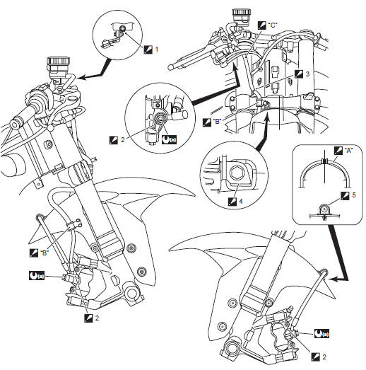
Suzuki GSX-R 1000 Service Manual: Front brake hose routing diagram
|
 Hose clamp
 Stopper
 Stopper
 Hose clamp
 White marking
 Clamp the
 Pass the
 23 N·m (2.3 Kgf-m,

 Rear brake hose routing diagram
Hose clamp
: face the clamp end backward.
Stopper
: after the brake hose union has contacted
to the stopper, tighten the union bolt.
Brake pad pin
Plug
...
Other materials:
Water pump disassembly and assembly
Refer to “water pump removal and installation” .
Disassembly
Remove the air bleeder bolt (1) if necessary.
Remove the water pump case screws.
Remove the o-ring (2).
Hold the impeller (3) with water pump pliers and
remove the impeller securing bolt (4).
Remove t ...
Combination meter removal and installation
Removal
Remove the combination meter mounting bolt (1).
Bushing
Disconnect the coupler (2) and remove the
combination meter assembly (3).
Installation
Install the combination meter in the reverse order of
removal.
Note
fix the boot of ...
Schematic and routing diagram
Engine lubrication system chart diagram
Engine lubrication circuit diagram
...