
Suzuki GSX-R 1000 Service Manual: Fuse
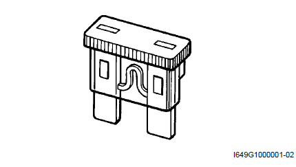
- When a fuse is blown, always investigate the cause to correct it and then replace the fuse.
- Do not use a fuse of different capacity.
- Do not use wire or any other substitute for the fuse.
Switch
Never apply grease material to switch contact points to prevent damage.
 Clamp
Clamp
Clamp the wire harness at such positions as indicated in “wiring harness
routing diagram” in section 9a .
Bend the clamp properly so that the wire harness is
clamped securely.
...
 Ecm / various sensors
Since each component is a high-precision part, great
care should be taken not to apply any severe impacts
during removal and installation.
Be careful not to touch the electrical termi ...
Other materials:
Crankcase breather (pcv) cover inspection
Inspect the crankcase breather (pcv) cover in the
following procedures:
remove the crankcase breather (pcv) cover. Refer to “crankcase breather
(pcv) hose / reed valve / cover removal and installation” .
Inspect the crankcase breather (pcv) cover for
carbon deposit. If carbon ...
Front wheel components
Front axle
Brake disc bolt
Brake disc
Dust seal
Bearing
Spacer
Air valve
Front wheel
Wheel balancer
Front tire
Collar
Front axle bolt
18 N·m (1.8 Kgf-m,
13.0 Lbf-ft)
100 N·m
(10.0 Kgf-m, 72.5 Lbf-ft)
Apply ...
Charging system symptom diagnosis
Condition
Possible cause
Correction / reference item
Generator does not
charge
Open- or short-circuited lead wires, or
loose lead connections.
Repair, replace or connect properly.
Short-circuited, grounded or open
generator coil.
Replace
...