Suzuki GSX-R 1000 Service Manual: Rear shock absorber adjustment
After installing the rear suspension, adjust the spring pre-load and damping force as follows:
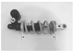
Spring pre-load adjustment
- The set length 179.3 Mm (7.06 In) provides the maximum spring pre-load.
- The set length 189.3 Mm (7.45 In) provides the minimum spring pre-load.
Std position 184.3 Mm (7.26 In)
Damping force adjustment
Note
|
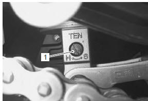
Rebound side
Fully turn the rebound damping force adjuster (1) clockwise. From that position (stiffest), turn it out to standard setting position.
Std position 2-3/4 turns out from stiffest position
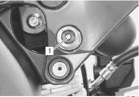
Compression side (low speed)
Fully turn the compression damping force (low speed) adjuster (1) clockwise. From that position (stiffest), turn it out to standard setting position.
Std position 2-1/4 turns out of from stiffest position
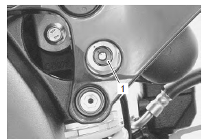
Compression side (high speed)
Fully turn the compression damping force (high speed) adjuster (1) clockwise. From that position (stiffest), turn it out to standard setting position.
Std position 3 turns out of from stiffest position
 Rear shock absorber bearing removal and installation
Removal
Remove the rear shock absorber. Refer to “rear shock absorber removal
and installation” .
Remove the spacer (1).
Remove the rear shock absorber bearing with the
spec ...
 Rear shock absorber disposal
Refer to “rear shock absorber removal and installation” .
The rear shock absorber unit contains high-pressure
nitrogen gas.
Mishandling can cause explosion.
Keep away from f ...
Other materials:
The sport of motorcycling
Your motorcycle and this owner's
manual have been designed by
people like you who enjoy motorcycling.
People become motorcyclists
for many reasons. For
starters, street riding is fun and
invigorating. But no matter why
you became a motorcyclist, or
how experienced you are, you will
eventu ...
Gearshift lever construction
Gearshift lever bracket
Gearshift lever shaft
Washer
Snap ring
Gearshift lever
Footrest top surface
65 – 75 Mm (2.6 – 3.0 In)
28 N·m (2.8 Kgf-m,
20.0 Lbf-ft)
40 N·m
(4.0 Kgf-m, 29.0 Lbf-ft)
Apply grease.
Grease.
...
Exhaust emission control system
description
The exhaust emission control system is composed of the pair system, exhaust
control system, ho2 sensor, threeway
catalyst system and isc system. The fresh air is drawn into the exhaust ports
through the pair control solenoid
valve and pair reed valves. The pair control solenoid valve is operat ...