Suzuki GSX-R 1000 Service Manual: Schematic and routing diagram
Engine lubrication system chart diagram
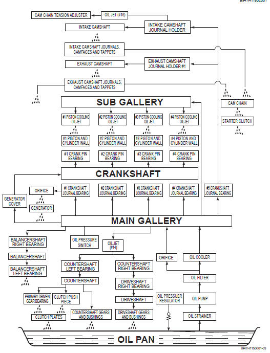
Engine lubrication circuit diagram
 Engine lubrication system
Precautions
Precautions for engine oil
Refer to “fuel and oil recommendation” in section 0a . ...
 Diagnostic information and procedures
Engine lubrication symptom diagnosis
Oil pressure check
Check the engine oil pressure periodically. This will give
a good indication of the condition of the moving parts.
Note
before ...
Other materials:
Precautions
Precautions for engine electrical device
Refer to “general precautions” in section 00 (page 00-1) and “precautions for
electrical circuit service” in section 00
(page 00-2).
Component location
Engine electrical components location
Refer to “electrical components location” in section 0a .
Dia ...
Excva pulley inspection
Inspect the excva pulley in the following procedures:
remove the excva pulley. Refer to “excv cable removal and installation”
.
Visually inspect the excva pulley for wear and
damage. If there is anything unusual, replace the
pulley with a new one.
Install the pulle ...
Steering tension adjustment
Check the steering movement in the following
procedures:
by supporting the motorcycle with a jack, lift the front
wheel unit is off the floor 20 – 30 mm (0.8 – 1.2 In).
Remove the steering damper. Refer to “steering damper construction” .
Check to make sure that the cabl ...