Suzuki GSX-R 1000 Service Manual: Schematic and routing diagram
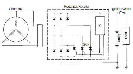
Charging system diagram
Component location
Charging system components location
Refer to “electrical components location” in section 0a .
 Charging system
...

Other materials:
DTC “c60” (p0480): cooling fan relay
circuit malfunction
Detected condition and possible cause
Detected condition
Possible cause
Cooling fan relay signal is not input to ecm.
Cooling fan relay circuit open or short.
Ecm malfunction.
Wiring diagram
Troubleshooting
Caution
when using ...
Location of parts
ciutch lever
left handlebar switches
indicator lights
tachometer
ignition switch
front brake fluid reservoir
right handlebar switches
throttle grip
front brake lever
fuel tank cap
front suspension spring pre-load and rebound damping
force ...
Clutch removal
Drain engine oil. Refer to “engine oil and filter replacement” in
section 0b .
Lift and support the fuel tank with the prop stay.
Refer to “fuel tank removal and installation” in section 1g .
Disconnect the ckp sensor coupler (1).
Remove the clutch cover (2).
...