Suzuki GSX-R 1000 Service Manual: Diagnostic information and procedures
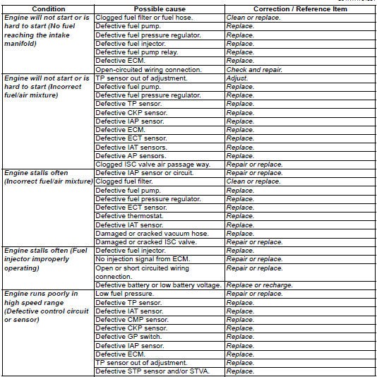
Fuel system diagnosis
 Schematic and routing diagram
Fuel tank drain hose and breather hose routing diagram
Fuel tank water drain hose
Fuel tank breather hose no. 1
Fuel tank breather hose no. 2
Fuel tank breather hose n ...

Other materials:
DTC “c42” (p1650): ig switch circuit
malfunction
Detected condition and possible cause
Detected condition
Possible cause
Ignition switch signal is not input to the ecm.
Ignition system circuit open or short.
Ecm malfunction.
When the id agreement is not verified.
Ecm does not re ...
Special situations require special care
Of course, there are some times
when full-force braking is not the
correct technique. When the road
surface is wet, loose, or rough,
you should brake with care. When
you're leaned over in a corner,
avoid braking. Straighten up
before braking. Better yet, slow
down before entering the corner. ...
Conclusion
Traffic, road and weather conditions
vary. Other motorists'
actions are unpredictable. Your
motorcycle's condition can
change. These factors can best
be dealt with by giving every ride
your full attention.
Circumstances beyond your control
could lead to an accident. You
need to prepare fo ...