Suzuki GSX-R 1000 Service Manual: Schematic and routing diagram
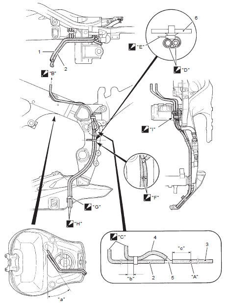
Fuel tank drain hose and breather hose routing diagram
|
 Set the
 Match the
 Arrange the
 Face the
 Set the
 Stick the
 Clamp the
 Pass the
 General description
Fuel injection system description
Fuel system
The fuel delivery system consists of the fuel tank (1), fuel pump (2), fuel
filter (3), fuel feed hose (4), fuel delivery pipes
(5) including fuel in ...
 Diagnostic information and procedures
Fuel system diagnosis
...
Other materials:
Conrod crank pin bearing removal and
installation
Refer to “engine bottom side disassembly” (page 1d-
49).
Refer to “engine bottom side assembly” .
Removal
Remove the conrod crank pin bearings (1).
Note
do not remove the bearings (1) unless
absolutely necessary.
Make a note of where the bearings are
removed ...
Special tools and equipment
Recommended service material
Note
required service material is also described in the following.
“Exhaust system components”
Special tool
...
Starter motor removal and installation
Removal
Turn the ignition switch off and disconnect the
battery (–) lead wire (1).
Lift and support the fuel tank. Refer to “fuel tank
removal and installation” in section 1g (page 1g-
9).
Disconnect the starter motor lead wire (2).
Remove the starter motor (3).
...