Suzuki GSX-R 1000 Service Manual: Rear sprocket / rear sprocket mounting drum removal and installation
Removal
- Remove the rear wheel assembly. Refer to “rear wheel assembly removal and installation” in section 2d .
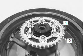
- Loosen the rear sprocket nuts.
- Draw out the rear sprocket mounting drum (1) along with the rear sprocket (2) from the wheel hub.
- Remove the rear sprocket nuts and separate the rear sprocket (2) from its mounting drum (1).
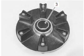
- Remove the retainer (3).
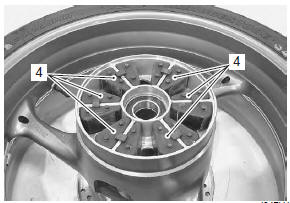
- Remove the wheel dampers (4).
Installation
Install the rear sprocket and rear sprocket mounting drum in the reverse order of removal. Pay attention to the following points:
- apply grease to the contacting surface between the rear wheel hub and rear sprocket mounting drum.
 : Grease 99000–25010 (suzuki
super
grease “a” or equivalent)
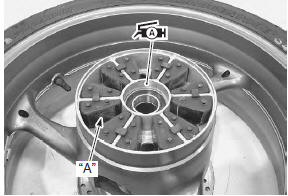
- Apply special tire lubricant or neutral soapy liquid to the wheel damper surfaces “a”.
| Caution never use oil, grease or gasoline on the wheel damper in place of the tire lubricant or neutral soapy liquid. |
- Apply grease to the retainer.
 : Grease 99000–25010 (suzuki
super
grease “a” or equivalent)
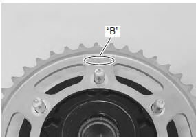
- Install the rear sprocket so that the letters “b” face outside.
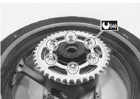
- Tighten the rear sprocket nuts to the specified torque.
Tightening torque rear sprocket nut (a): 60 n·m (6.0 Kgf-m, 43.0 Lbfft)
- Install the rear wheel assembly. Refer to “rear wheel assembly removal and installation” in section 2d .
 Engine sprocket removal and installation
Removal
Remove the gearshift link arm (1) from the gearshift
shaft.
Note
mark the gearshift shaft head at which the
gearshift link arm slit set for correct
reinstallation.
...
 Drive chain related parts inspection
Refer to “rear sprocket / rear sprocket mounting drum removal and
installation” .
Dust seal
Inspect the dust seal for wear or damage. If any damage
is found, replace the dust seal with a new one. ...
Other materials:
Cam chain guide inspection
Inspect the cam chain guide in the following procedures:
remove the cam chain guides. Refer to “cam chain guide / cam chain
tensioner removal and installation” .
Check the contacting surface of the cam chain
guides. If it is worn or damaged, replace it with a new
one.
...
Front brake master cylinder / brake lever disassembly and assembly
Refer to “front brake master cylinder assembly removal and installation” .
Disassembly
Remove the reservoir cap (1), plate (2), diaphragm
(3) and reservoir tank (4).
Remove the brake light switch (5) and brake lever
(6).
Remove the dust boot (7) and push rod (8).
...
Gearshift lever construction
Gearshift lever bracket
Gearshift lever shaft
Washer
Snap ring
Gearshift lever
Footrest top surface
65 – 75 Mm (2.6 – 3.0 In)
28 N·m (2.8 Kgf-m,
20.0 Lbf-ft)
40 N·m
(4.0 Kgf-m, 29.0 Lbf-ft)
Apply grease.
Grease.
...