Suzuki GSX-R 1000 Service Manual: Engine sprocket removal and installation
Removal
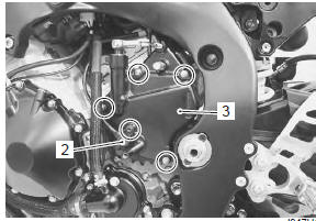
- Remove the gearshift link arm (1) from the gearshift shaft.
| Note mark the gearshift shaft head at which the gearshift link arm slit set for correct reinstallation. |
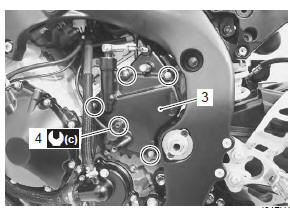
- Remove the speed sensor (2).
- Remove the engine sprocket cover (3).
- Support the motorcycle with a jack or wooden block.
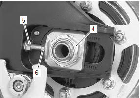
- Loosen the rear axle nut (4) and left and right chain adjuster lock-nuts (5).
- Loosen the chain adjusters (6) to provide additional chain slack.
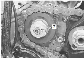
- Remove the speed sensor rotor (7) by removing its bolt while depressing the rear brake pedal.
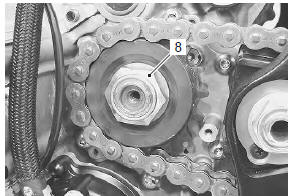
- Remove the engine sprocket nut (8) while depressing the rear brake pedal.
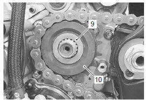
- Remove the washer (9).
- Remove the engine sprocket (10).
Installation
Install the engine sprocket in the reverse order of removal. Pay attention to the following points:
- apply thread lock to the driveshaft.
 : Thread lock cement
99000–32110
(thread lock cement super “1322” or
equivalent)
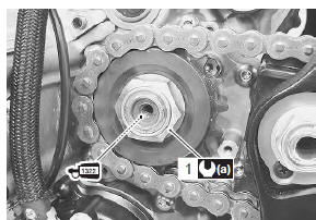
- Tighten the engine sprocket nut (1) to the specified torque.
Tightening torque engine sprocket nut (a): 145 n·m (14.5 Kgf-m, 105.0 Lbf-ft)
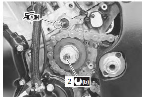
- Tighten the speed sensor rotor bolt (2) to the specified torque.
Tightening torque speed sensor rotor bolt (b): 28 n·m (2.8 Kgf-m, 20.0 Lbf-ft)
- Before installing the engine sprocket cover, apply a small quantity of grease to the clutch push rod.
 : Grease 99000–25010 (suzuki
super
grease “a” or equivalent)
- Install the engine sprocket cover (3).
- Tighten the speed sensor mounting bolt (4) to the specified torque.
Tightening torque speed sensor mounting bolt (c): 6.5 N·m (0.65 Kgf-m, 4.5 Lbf-ft)
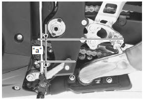
- Fit the gearshift link arm to the gearshift shaft so that the gearshift lever is located at height “a” below the footrest.
Gearshift lever height “a” standard: 65 – 75 mm (2.6 – 3.0 In)
- Adjust the drive chain slack. Refer to “drive chain inspection and adjustment” in section 0b (page 0b- 14).
 Drive chain related components
Drive chain
Engine sprocket
Rear sprocket
Dust seal
Bearing
Retainer
Sprocket mounting drum
Wheel damper
145 N·m (14.5 Kgf-m,
105.0 Lbf-ft ...
 Rear sprocket / rear sprocket mounting drum removal and installation
Removal
Remove the rear wheel assembly. Refer to “rear wheel assembly removal
and installation” in section 2d .
Loosen the rear sprocket nuts.
Draw out the rear sprocket mountin ...
Other materials:
Side-stand / ignition interlock system parts
inspection
Check the interlock system for proper operation. If the
interlock system does not operate properly, check each
component for damage or abnormalities. If any
abnormality is found, replace the component with a new
one.
Side-stand switch
Turn the ignition switch off.
Remove the left si ...
Conrod and crankshaft inspection
Refer to “engine bottom side disassembly” (page 1d-
49).
Refer to “engine bottom side assembly” .
Conrod small end I.D.
Measure the conrod small end inside diameter using the
small bore gauge.
If the conrod small end inside diameter exceeds the
service limit, replace the conrod.
Special ...
Schematic and routing diagram
Cooling circuit diagram
Water hose routing diagram
Thermostat air bleeder hole
Cushion
O-ring
Radiator heat guard
: be careful not to damage the pawls when removing.
Yellow
marking
White
marking
Clamp end
should face downward
...