
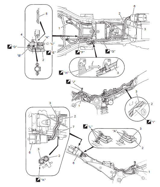
Suzuki GSX-R 1000 Service Manual: Evap canister hose routing diagram (only for e-33)
|
 Face the
 Face the
 Pass the
 Pass the
 Stick the
 Pass the
 Face the
 Face the
 Face the
 Pair system hose routing diagram
Pair control solenoid valve
Pair reed valve
White marking (hidden side)
Yellow marking
Blue marking
Red marking
Face the
clamp end to the top.
Mak ...

Other materials:
Tampering with noise control system prohibited
Federal law prohibits the following
acts or the causing there of;
The removal or rendering inoperative
by any person other
than for purposes of maintenance,
repair, or replacement,
of any device or element of
·design incorporated into any
new vehicle for the purpose of
noise ...
Dtc “c36” (p1764), “c37” (p1765), “c38” (p1766) or “c39” (p1767): secondary
fuel injector circuit
malfunction
Detected condition and possible cause
Detected condition
Possible cause
Some failure exists in the fuel injector signal in a high
load, high revolution condition.
Injector circuit open or short.
Injector malfunction.
Ecm malfunction.
...
Clutch cable removal and installation
Removal
Remove the left side cowling. Refer to “exterior parts removal and
installation” in section 9d .
Disconnect the clutch cable from the clutch lever.
Refer to “handlebar removal and installation” in section 6b .
Remove the clutch cable as shown in the throttle cable ro ...