Suzuki GSX-R 1000 Service Manual: DTC “c23” (p1651-h/l): to sensor circuit malfunction
Detected condition and possible cause
|
Detected condition |
Possible cause |
||
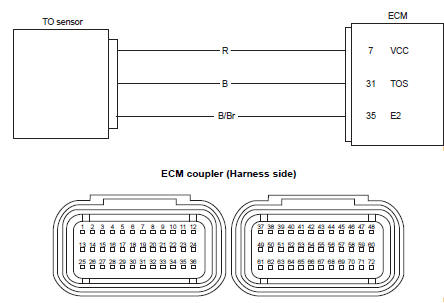
| C23 | The sensor voltage should be the
following for 2 sec. And more, after ignition
switch is turned on.
0.2 V ≤ Sensor voltage < 4.8 V |
|
|
| P1651 | H | Sensor voltage is higher than specified value. | |
| L | Sensor voltage is lower than specified value. | ||
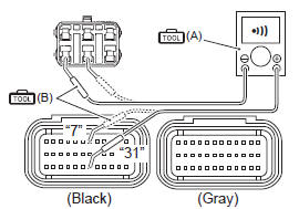
Wiring diagram
Troubleshooting
| Caution when using the multi-circuit tester, do not strongly touch the terminal of the ecm coupler with a needle pointed tester probe to prevent terminal damage. |
| Note after repairing the trouble, clear the dtc using sds tool. Refer to “use of sds diagnosis reset procedures” . |
C23 (use of mode select switch)
|
Step |
Action |
Yes |
No |
|
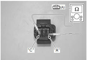
1 |
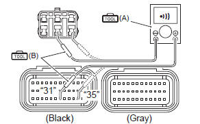
Special tool Tester knob indication resistance (Ω) To sensor resistance 16.5 – 22.3 KΩ (terminal “a” – terminal “c”)
Is the resistance ok? |
Go to step 2. | Replace the to sensor with a new one. Refer to “to sensor removal and installation” in section 1c (page 1c- 6). |
 (a): 09900–25008 (multi
P1651-h (use of sds)
|
Step |
Action |
Yes |
No |
|
1 |
Special tool Tester knob indication
continuity test (
Special tool Tester knob indication
continuity test ( Ecm coupler (harness side)
Is the continuity ok? |
Go to step 2. | B wire shorted to vcc, or b/br wire open. |
 (a): 09900–25008 (multi
 )
)
 )
)
P1651-l (use of sds)
|
Step |
Action |
Yes |
No |
|
1 |
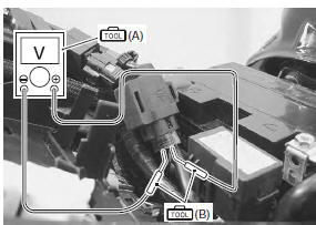
Special tool Tester knob indication continuity test (
Special tool Tester knob indication continuity test (
) Ecm coupler (harness side)
Is the continuity ok? |
Go to step 2. | R or b wire open, or b wire shorted to ground. |
|
2 |
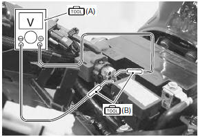
Special tool Tester knob indication
voltage ( To sensor voltage (normal) 0.4 – 1.4 V ((+) terminal: b – (–) terminal: b/br)
Special tool To sensor voltage (leaning) 3.7 – 4.4 V ((+) terminal: b – (–) terminal: b/br)
Is the voltage ok? |
|
|
 )
)
DTC “c24” (p0351), “c25” (p0352), “c26” (p0353) or “c27” (p0354): ignition system malfunction
| Note refer to “no spark or poor spark” in section 1h for details. |
 DTC “c22” (p1450-h/l): ap sensor circuit
malfunction
DTC “c22” (p1450-h/l): ap sensor circuit
malfunction
Detected condition and possible cause
Detected condition
Possible cause
C22
Ap sensor voltage is not within the
following range.
0.5 V ≤ Sensor voltage < ...
 DTC “c28” (p1655): secondary throttle
valve actuator (stva) malfunction
DTC “c28” (p1655): secondary throttle
valve actuator (stva) malfunction
Detected condition and possible cause
Detected condition
Possible cause
The operation voltage does not reach the stva.
Ecm does not receive communication signal from the ...
Other materials:
Specifications
Service data
Wheel
unit: mm (in)
Tire
Tightening torque specifications
Note
the specified tightening torque is described in the following.
“Front wheel components” “front wheel assembly construction”
“rear wheel components” “rear wheel assembly c ...
Idle speed
Adjust the engine idle speed periodically on the engine at normal operating
temperature.
To adjust the idle speed:
Lift the fuel tank by referring to
the air cleaner section.
Start the engine and warm it
up by running at idling speed
for 10 minutes in summer
(where ambie ...
Radiator inspection and cleaning
Radiator hose inspection
Refer to “cooling system inspection” in section 0b .
Radiator inspection
Inspect the radiator for water leaks. If any defects are
found, replace the radiator with a new one.
If the fins are bent or dented, repair them by carefully
straightening them with the blade of ...