Suzuki GSX-R 1000 Service Manual: DTC “c22” (p1450-h/l): ap sensor circuit
malfunction
Detected condition and possible cause
|
Detected condition |
Possible cause |
| C22 |
Ap sensor voltage is not within the
following range.
0.5 V ≤ Sensor voltage < 4.85 V
| Note
note that atmospheric pressure
varies depending on weather
conditions as well as altitude.
Take that into consideration
when inspecting voltage. |
|
- Clogged vacuum passage with dust.
- Ap sensor circuit open or shorted to ground.
- Ap sensor malfunction.
- Ecm malfunction.
- Ap sensor circuit is open or shorted to vcc or ground
circuit open.
- Ap sensor circuit is shorted to ground or vcc circuit
open.
|
| P1450 |
H |
Sensor voltage is higher than specified
value. |
|
L |
Sensor voltage is lower than specified
value. |
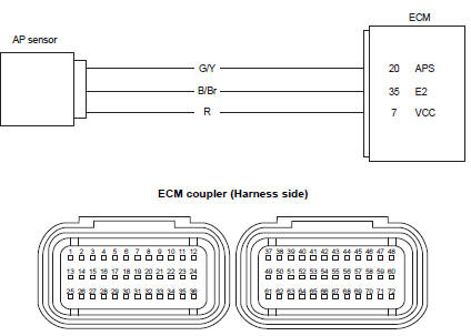
Wiring diagram
Troubleshooting
| Caution
when using the multi-circuit tester, do not strongly touch the terminal
of the ecm coupler with a
needle pointed tester probe to prevent terminal damage. |
| Note
after repairing the trouble, clear the dtc using sds tool. Refer to “use
of sds diagnosis reset procedures” . |
C22 (use of mode select switch)
|
Step |
Action |
Yes |
No |
|
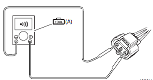
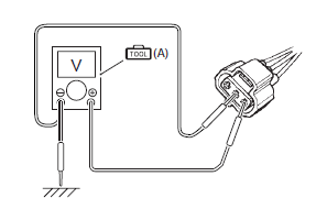
1 |
- Turn the ignition switch off.
- Remove the front seat. Refer to “exterior parts removal and
installation” in section 9d .
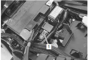
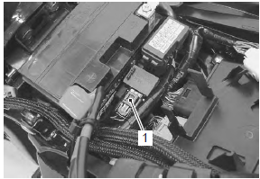
- Remove the starter relay from the bracket.
- Check the ap sensor coupler (1) for loose or poor
contacts.
If ok, then measure the ap sensor input voltage.
- Disconnect the ap sensor coupler.
- Turn the ignition switch on.
- Measure the input voltage between the r wire and
ground.
If ok, then measure the voltage between the r wire and
b/br wire.
Special tool
 (a): 09900–25008 (multi (a): 09900–25008 (multi
circuit tester set)
Tester knob indication
voltage (  ) )
Ap sensor input voltage
4.5 – 5.5 V
((+) terminal: r – (–) terminal: ground, (+) terminal: r
– (–) terminal: b/br)
Is the voltage ok? |
Go to step 3. |
- Loose or poor
contacts on the ecm
couplers.
- Open or short circuit
in the r or b/br wire.
|
P1450-h (use of sds)
|
Step |
Action |
Yes |
No |
|
1 |
- Turn the ignition switch off.
- Remove the front seat. Refer to “exterior parts removal and
installation” in section 9d .
- Remove the starter relay from the bracket.
- Check the ap sensor coupler (1) for loose or poor
contacts.
If ok, then check the ap sensor lead wire continuity.
- Disconnect the ap sensor coupler.
- Check the continuity between the r wire and g/y wire.
If the sound is not heard from the tester, the circuit
condition is ok.
Special tool
 (a): 09900–25008 (multi (a): 09900–25008 (multi
circuit tester set)
Tester knob indication
continuity ( ) )
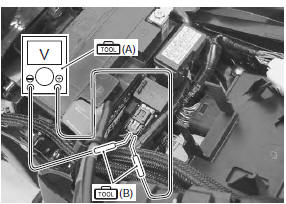
- Disconnect the ecm couplers. Refer to “ecm removal and
installation” in section 1c .
- Insert the needle pointed probes to the lead wire coupler.
- Check the continuity between the g/y wire and terminal
“20”.
If ok, then check the continuity between the b/br wire
and terminal “35”.
Special tool
(a): 09900–25008 (multi
circuit tester set)
(b): 09900–25009
(needle-point probe set)
Tester knob indication
continuity test ( ) )
Ecm coupler (harness side)
Is the continuity ok? |
Go to step 3. |
G/y wire shorted to
vcc, or b/br wire open. |
P1450-l (use of sds)
|
Step |
Action |
Yes |
No |
|
1 |
- Turn the ignition switch off.
- Remove the front seat. Refer to “exterior parts removal and
installation” in section 9d .
- Remove the starter relay from the bracket.
- Check the ap sensor coupler (1) for loose or poor
contacts.
If ok, then check the ap sensor lead wire continuity.
- Disconnect the ap sensor coupler.
- Check the continuity between the g/y wire and ground.
Also, check the continuity between the g/y wire and b/
br wire. If the sound is not heard from the tester, the
circuit condition is ok.
Special tool
 (a): 09900–25008 (multi (a): 09900–25008 (multi
circuit tester set)
Tester knob indication
continuity ( ) )
- Disconnect the ecm couplers. Refer to “ecm removal and
installation” in section 1c .
- Insert the needle pointed probes to the lead wire coupler
- Check the continuity between the r wire and terminal
“7”. Also, check the continuity between the g/y wire and
terminal “20”.
Special tool
(a): 09900–25008 (multi
circuit tester set)
v(b): 09900–25009 (needle-point probe set)
Tester knob indication
continuity ( )
Ecm coupler (harness side)
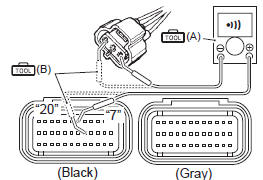
Is the continuity ok? |
Go to step 2. |
R and g/y wire open, g/
y wire shorted to
ground. |
|
2 |
- Connect the ecm couplers.
- Turn the ignition switch on.
- Measure the input voltage between the r wire and
ground.
If ok, then measure the voltage between the r wire and
b/br wire.
Special tool
(a): 09900–25008 (multi
circuit tester set)
Tester knob indication
voltage ( ) )
Ap sensor input voltage
4.5 – 5.5 V
((+) terminal: r – (–) terminal: ground, (+) terminal: r
– (–) terminal: b/br)
Is the voltage ok? |
Go to step 3. |
- Loose or poor
contacts on the ecm
couplers.
- Open or short circuit
in the r or b/br wire.
|
|
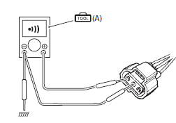
3 |
- Turn the ignition switch off.
- Connect the ecm couplers and ap sensor coupler.
- Insert the needle pointed probes to the lead wire coupler.
- Run the engine at idle speed and measure the ap
sensor output voltage between the g/y wire and b/br
wire.
Special tool
(a): 09900–25008 (multi
circuit tester set)
(b): 09900–25009
(needle-point probe set)
Tester knob indication
voltage ( )
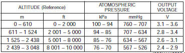
Ap sensor output voltage
approx. 3.6 V at 100 kpa (760 mmhg)
((+) terminal: g/y – (–) terminal: b/br)
Is the voltage ok? |
Go to step 4. |
- Check the vacuum
port for crack or
damage.
- Open or short circuit
in the g/y wire.
- If vacuum hose and lead wire are ok, replace the ap sensor with
a new one. Refer to “ap sensor removal and installation” in section
1c .
|
|
4 |
- Turn the ignition switch off.
- Remove the ap sensor. Refer to “ap sensor removal and
installation” in section 1c .
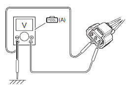
- Connect the vacuum pump gauge to the vacuum port of
the ap sensor.
- Arrange 3 new 1.5 V batteries in series (1) (check that
total voltage is 4.5 – 5.0 V) and connect (–) terminal to
the ground terminal “b” and (+) terminal to the vcc
terminal “a”.
- Check the voltage between vout terminal “c” and
ground. Also, check if voltage reduces when vacuum is
applied up to 53 kpa (400 mmhg) by using vacuum
pump gauge.
Special tool
(a): 09917–47011 (vacuum
pump gauge set)
(b): 09900–25008 (multi
circuit tester set)
Tester knob indication
voltage ( )
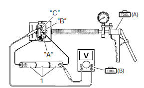
Is the voltage ok? |
- G/y, r or b/br wire
open or shorted to
ground, or poor “7”,
“20” or “35”
connection.
- If wire and
connection are ok,
intermittent trouble or
faulty ecm.
- Recheck each
terminal and wire
harness for open
circuit and poor
connection.
- Replace the ecm with a known good one, and inspect it again.
Refer to “ecm removal and installation” in section 1c .
|
If check result is not satisfactory, replace the ap sensor with a
new one. Refer to “ap sensor removal and installation” in section 1c . |
Detected condition and possible cause
Detected condition
Possible cause
C21
Output voltage is not with in the following
range.
0.15 V ≤ Sensor voltage < ...
Detected condition and possible cause
Detected condition
Possible cause
C23
The sensor voltage should be the
following for 2 sec. And more, after ignition
switch i ...
Other materials:
Engine coolant recommendation
Engine coolant
Use an anti-freeze/engine coolant compatible with an
aluminum radiator, mixed with distilled water only.
Water for mixing
Use distilled water only. Water other than distilled water
can corrode and clog the aluminum radiator.
Anti-freeze / engine coolant
The engine coolant perfo ...
Air valve removal and installation
Removal
Remove the wheel assembly. Refer to “front wheel assembly removal and
installation” and “rear wheel assembly removal and installation” .
Remove the tire. Refer to “tire removal and installation” .
Remove the air valve (1) from the wheel.
Installation
Install th ...
Washing the motorcycle
When washing the motorcycle,
follow the instructions below:
Remove dirt and mud from the
motorcycle with running water.
You may use a soft sponge or
brush. Do not use hard materials
which can scratch the
paint.
Wash the entire motorcycle
with a mild detergent or car
...
 DTC “c21” (p0110-h/l): iat sensor circuit
malfunction
DTC “c21” (p0110-h/l): iat sensor circuit
malfunction DTC “c23” (p1651-h/l): to sensor circuit
malfunction
DTC “c23” (p1651-h/l): to sensor circuit
malfunction