Suzuki GSX-R 1000 Service Manual: Balancer shaft journal bearing removal and installation
Refer to “engine bottom side disassembly” (page 1d- 49).
Refer to “engine bottom side assembly” .
Removal
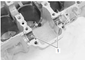
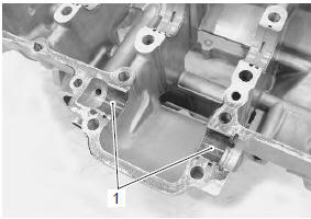
Remove the balancer shaft journal bearings (1).
Note
|
| Caution when removing the bearings, be careful not to scratch the bearings. |
Installation
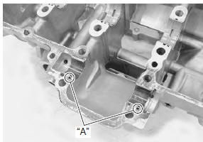
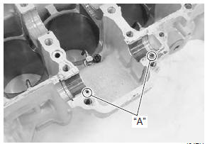
When installing the bearings to the crankcases, be sure to install the tab “a” first, and then press in the other opposite side of the bearing.
| Note inspect and select the balancer shaft journal bearing if necessary. Refer to “balancer shaft journal bearing inspection and selection” . |
 Balancer shaft inspection
Refer to “balancer shaft disassembly and assembly” .
Balancer shaft
Inspect the balancer shaft for wear or damage. Replace
the balancer shaft if there is anything unusual.
Damper
Inspect the damp ...
 Balancer shaft journal bearing inspection
and selection
Balancer shaft journal bearing inspection
and selection
Refer to “engine bottom side disassembly” (page 1d-
49).
Refer to “engine bottom side assembly” .
Inspection
Inspect the bearing surfaces for any signs of fusion,
pitting, burn or flaws. If any ...
Other materials:
DTC “c31” (p0705): gp switch circuit
malfunction
Detected condition and possible cause
Detected condition
Possible cause
No gear position switch voltage
Gp switch voltage is not within the following range.
Gp switch voltage > 0.6 V
Gp switch circuit open or short.
Gp switch malfunction.
...
Cylinder head disassembly and assembly
Refer to “engine top side disassembly” .
Refer to “engine top side assembly” .
Caution
identify the position of each removed part.
Organize the parts in their respective groups
(i.E., Intake, exhaust, no. 1 Or no. 2) So that
they can be installed in their original
locations ...
Diagnostic information and procedures
Starting system symptom diagnosis
Condition
Possible cause
Correction / reference item
Engine does not turn
though the starter motor
runs
Faulty starter clutch.
Replace.
Starter button is not
effective
Run down battery
Repair or replac ...