Suzuki GSX-R 1000 Service Manual: Cylinder head disassembly and assembly
Refer to “engine top side disassembly” .
Refer to “engine top side assembly” .
| Caution identify the position of each removed part. Organize the parts in their respective groups (i.E., Intake, exhaust, no. 1 Or no. 2) So that they can be installed in their original locations. |
Disassembly
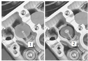
- Remove the tappet (1) and shim (2) by fingers or magnetic hand.
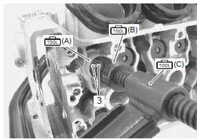
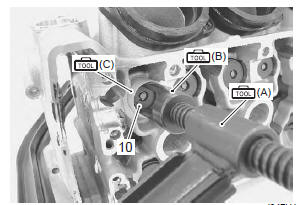
- Insert the special tool (a) between the valve springs and cylinder head.
- Using the special tools, compress the valve springs and remove the two cotter halves (3) from the valve stem.
| Caution be careful not to damage the tappet sliding surface with the special tool. |
Special tool
 (a): 09919–28620 (sleeve protector)
 (b): 09916–14522 (valve lifter
attachment)
 (c): 09916–14510 (valve lifter)
 : 09916–84511 (tweezer)
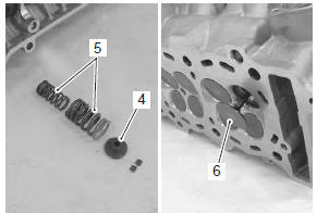
- Remove the valve spring retainer (4) and valve springs (5).
- Pull out the valve (6) from the combustion chamber side.
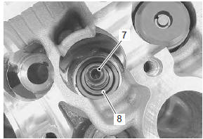
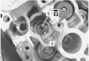
- Remove the oil seal (7) and spring seat (8).
- Remove the other valves in the same manner as described previously.
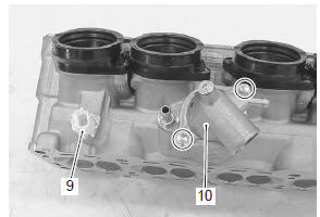
- Remove the ect sensor (9).
- Remove the thermostat cover (10).
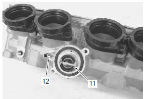
- Remove the thermostat (11).
- Remove the bypass hose union (12).
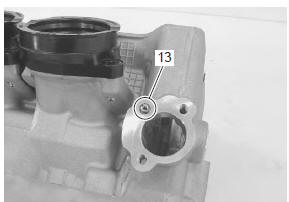
- Remove the oil jet (13).
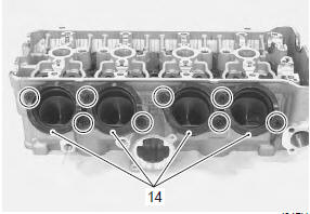
- Remove the intake pipes (14).
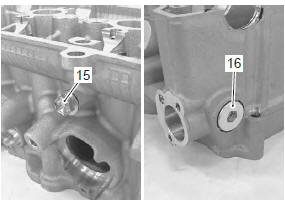
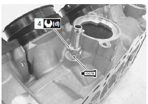
- Remove the oil gallery plug (15).
- Remove the cam chain tension adjuster service cap (16).
Assembly
Assembly is in the reverse order of disassembly. Pay attention to the following points:
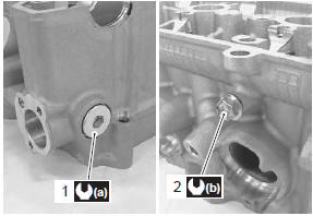
- tighten the cam chain tension adjuster service cap (1) and oil gallery plug (2) to the specified torque.
| Caution replace the gaskets with new ones. |
Tightening torque cam chain tension adjuster service cap (a): 23 n·m (2.3 Kgf-m, 16.5 Lbf-ft) oil gallery plug (cylinder head) (b): 10 n·m (1.0 Kgf-m, 7.0 Lbf-ft)
- Apply grease to o-rings of the intake pipes.
| Caution replace the o-rings with new ones. |
 : Grease 99000–25010 (suzuki
super
grease “a” or equivalent)
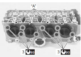
- Install the intake pipes with the up mark “a” facing top side.
- Tighten the intake pipe bolts (3) to the specified torque.
Tightening torque intake pipe bolt (c): 8.5 N·m (0.85 Kgf-m, 6.5 Lbf-ft)
- Apply engine oil to the o-ring and install the oil jet.
| Caution use new o-ring to prevent oil pressure leakage |
- Apply bond to the thread part of bypass hose union (4) and tighten it to the specified torque.
 : Sealant 99000–31140 (suzuki
bond
no.1207B or equivalent)
Tightening torque bypass hose union (d): 12 n·m (1.2 Kgf-m, 8.5 Lbfft)
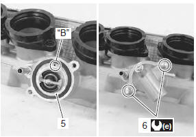
- Install the thermostat (5)
| Note the air bleeder hole “b” of the thermostat faces upside. |
- Tighten the thermostat cover bolts (6) to the specified torque.
Tightening torque thermostat cover bolt (e): 10 n·m (1.0 Kgf-m, 7.0 Lbf-ft)
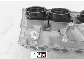
- Tighten the ect sensor (7) to the specified torque.
Tightening torque ect sensor (f): 18 n·m (1.8 Kgf-m, 13.0 Lbf-ft)
Caution
|
- Install the valve spring seat (8).
- Apply molybdenum oil to the oil seal (9), and press-fit it into the position.
| Caution do not reuse the removed oil seal. |
M/o: molybdenum oil (molybdenum oil solution)
- Insert the valve, with its stem coated with molybdenum oil solution all around and along the full stem length without any break.
| Caution when inserting the valve, take care not to damage the lip of the oil seal. |
M/o: molybdenum oil (molybdenum oil solution)
- Install each valve spring with the small-pitch portion “c” facing cylinder head.
|
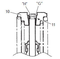
- Put on the valve spring retainer (10), and using the special tools, press down the springs, fit the cotter halves to the stem end, and release the lifter to allow the cotter halves to wedge in between retainer and stem.
Caution
|
Special tool
 (a): 09916–14510 (valve lifter)
 (b): 09916–14522 (valve lifter
attachment)
 (c): 09919–28620 (sleeve protector)
 : 09916–84511 (tweezer)
- Be sure that the rounded lip “g” of the cotter fits snugly into the groove “h” in the stem end.
|
- Install the other valves and springs in the same manner as described previously.
- Install the tappet shims and the tappets to their original positions.
Note
|
 Cam chain tensioner inspection
Inspect the cam chain tensioner in the following
procedures:
remove the cam chain tensioner. Refer to “cam chain guide / cam chain
tensioner removal and installation” .
Check the ...
 Cylinder head related parts inspection
Refer to “cylinder head disassembly and assembly” .
Cylinder head distortion
Decarbonize the combustion chambers.
Check the gasket surface of the cylinder head for
distortion. Use a str ...
Other materials:
Excva removal and installation
Removal
Turn the ignition switch off.
Remove the left side cowling. Refer to “exterior parts removal and
installation” in section 9d .
Connect the special tool (mode select switch) to the dealer mode
coupler. Refer to “self-diagnostic procedures” in section 1a .
After tur ...
Piston ring removal and installation
Removal
Remove the piston. Refer to “engine bottom side disassembly” .
Carefully spread the ring opening with your thumbs
and then push up the opposite side of the 1st ring to
remove it.
Note
do not expand the piston ring excessively
since it is apt to be broken down. ...
Iap sensor removal and installation
Removal
Lift and support the fuel tank. Refer to “fuel tank
removal and installation” in section 1g (page 1g-
9).
Disconnect the coupler (1) and vacuum hose (2).
Remove the iap sensor (3) from the air cleaner box.
Installation
Install the iap sensor in the reverse ord ...