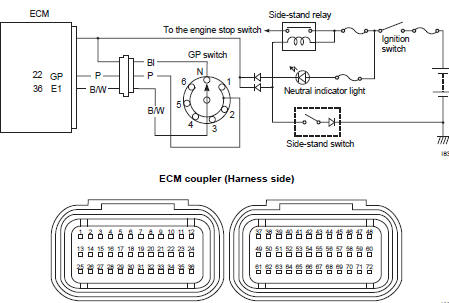
Suzuki GSX-R 1000 Service Manual: DTC “c31” (p0705): gp switch circuit malfunction
Detected condition and possible cause
|
Detected condition |
Possible cause |
| No gear position switch voltage
Gp switch voltage is not within the following range. Gp switch voltage > 0.6 V |
|
Wiring diagram
Troubleshooting
| Caution when using the multi-circuit tester, do not strongly touch the terminal of the ecm coupler with a needle pointed tester probe to prevent terminal damage. |
| Note after repairing the trouble, clear the dtc using sds tool. Refer to “use of sds diagnosis reset procedures” . |
|
Step |
Action |
Yes |
No |
|
1 |
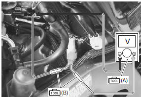
Special tool Tester knob indication voltage ( ) Gp switch voltage 0.6 V and more ((+) terminal: p – (–) terminal: b/w)
Is the voltage ok? |
|
|
 DTC “c29” (p1654-h/l): secondary throttle
position sensor (stps) circuit malfunction
DTC “c29” (p1654-h/l): secondary throttle
position sensor (stps) circuit malfunction
Detected condition and possible cause
Detected condition
Possible cause
C29
Output voltage is not within the following
range.
Difference between actual throttle op ...
 Dtc “c32” (p0201), “c33” (p0202), “c34” (p0203) or “c35” (p0204): primary
fuel injector circuit
malfunction
Dtc “c32” (p0201), “c33” (p0202), “c34” (p0203) or “c35” (p0204): primary
fuel injector circuit
malfunction
Detected condition and possible cause
Detected condition
Possible cause
Ckp signal is produced but fuel injector signal is
interrupted by 4 times or more continuity
...
Other materials:
Thermostat removal and installation
Removal
Drain a small amount of engine coolant. Refer to “cooling system
inspection” in section 0b .
Lift and support the fuel tank. Refer to “fuel tank
removal and installation” in section 1g (page 1g-
9).
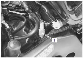
Remove the thermostat cover (1).
Remove the thermostat ( ...
Precautions
Precautions for wheel and tire
Proper tire pressure and proper tire loading are important
factors. Over loading tire can lead to tire
failure and loss of motorcycle control.
Under-inflated tires make smooth cornering difficult, and
can result in rapid tire wear.
...
Conrod crank pin bearing inspection and
selection
Refer to “engine bottom side disassembly” (page 1d-
49).
Refer to “engine bottom side assembly” .
Inspection
Inspect the bearing surfaces for any signs of fusion,
pitting, burn or flaws. If any, replace them with a
specified set of bearings.
Place the plastigauge axially along ...