Suzuki GSX-R 1000 Service Manual: DTC “c29” (p1654-h/l): secondary throttle position sensor (stps) circuit malfunction
Detected condition and possible cause
|
Detected condition |
Possible cause |
||
| C29 | Output voltage is not within the following
range. Difference between actual throttle opening and opening calculated by ecm is larger than specified value. 0.15 V ≤ Sensor voltage < 4.85 V |
|
|
| P1654 | H | Sensor voltage is higher than specified value. | |
| L | Sensor voltage is lower than specified value. | ||
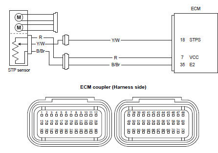
Wiring diagram
Troubleshooting
| Caution when using the multi-circuit tester, do not strongly touch the terminal of the ecm coupler with a needle pointed tester probe to prevent terminal damage. |
| Note after repairing the trouble, clear the dtc using sds tool. Refer to “use of sds diagnosis reset procedures” . |
C29 (use of mode select switch)
|
Step |
Action |
Yes |
No |
|
1 |
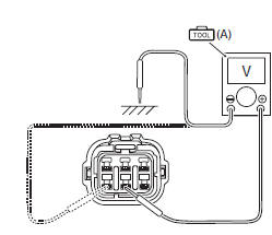
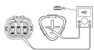
Special tool Tester knob indication
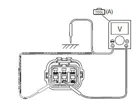
voltage ( Stp sensor input voltage 4.5 – 5.5 V ((+) terminal: r – (–) terminal: ground, (+) terminal: r – (–) terminal: b/br)
Is the voltage ok? |
Go to step 3. |
|
 (a): 09900–25008 (multi
 )
)
P1654-h (use of sds)
|
Step |
Action |
Yes |
No |
|
1 |
Special tool Tester knob indication
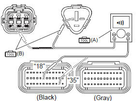
continuity (
Special tool
(a):
(b):
Tester knob indication
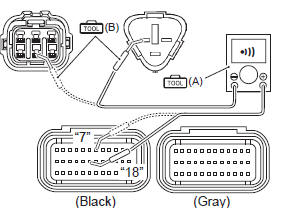
continuity test ( Ecm couplers (harness side)
Is the continuity ok? |
Go to step 3. | Y/w wire shorted to vcc, or b/br wire open. |
 (a): 09900–25008 (multi
 )
)
P1654-l (use of sds)
|
Step |
Action |
Yes |
No |
|
1 |
Special tool Tester knob indication
continuity test (
Special tool Tester knob indication
continuity test ( Ecm couplers (harness side)
Is the continuity ok? |
Go to step 2. | R or y/w wire open, or y/w wire shorted to ground. |
|
2 |
Special tool
Tester knob indication
voltage ( Stp sensor input voltage 4.5 – 5.5 V ((+) terminal: r – (–) terminal: ground, (+) terminal: r – (–) terminal: b/br)
Is the voltage ok? |
Go to step 3. | Open or short circuit in the r or b/br wire. |
|
3 |
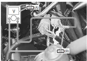
Special tool Tester knob indication
voltage ( Stp sensor output voltage secondary throttle valve is closed: approx. 0.7 V secondary throttle valve is opened: approx. 4.1 V ((+) terminal: y/w – (–) terminal: b/br)
Is the voltage ok? |
|
If check result is not satisfactory, replace the stp sensor with a new one. Refer to “stp sensor removal and installation” in section 1c . |
 )
)

 DTC “c28” (p1655): secondary throttle
valve actuator (stva) malfunction
DTC “c28” (p1655): secondary throttle
valve actuator (stva) malfunction
Detected condition and possible cause
Detected condition
Possible cause
The operation voltage does not reach the stva.
Ecm does not receive communication signal from the ...
 DTC “c31” (p0705): gp switch circuit
malfunction
DTC “c31” (p0705): gp switch circuit
malfunction
Detected condition and possible cause
Detected condition
Possible cause
No gear position switch voltage
Gp switch voltage is not within the following range.
Gp switch ...
Other materials:
Schematic and routing diagram
Cooling circuit diagram
Water hose routing diagram
Thermostat air bleeder hole
Cushion
O-ring
Radiator heat guard
: be careful not to damage the pawls when removing.
Yellow
marking
White
marking
Clamp end
should face downward
...
Gear position (gp) switch removal and installation
Removal
Turn the ignition switch off.
Lift and support the fuel tank. Refer to “fuel tank
removal and installation” in section 1g (page 1g-
9).
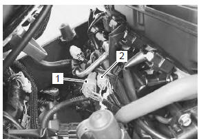
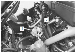
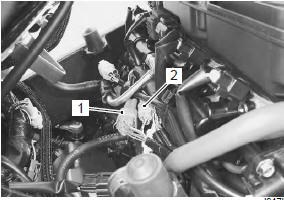
Disconnect the gear position switch lead wire
coupler (1).
Remove the engine sprocket cover. Refer to “engine sprocket r ...
Dimmer / passing light switch inspection
Inspect the dimmer/passing light switch in the following
procedures:
remove the air cleaner box. Refer to “air cleaner box removal and
installation” in section 1d .
Disconnect the left handlebar switch coupler (1).
(Yellow)
Inspect the dimmer/passing light switch ...