Suzuki GSX-R 1000 Service Manual: DTC “c21” (p0110-h/l): iat sensor circuit malfunction
Detected condition and possible cause
|
Detected condition |
Possible cause |
||
| C21 | Output voltage is not with in the following
range.
0.15 V ≤ Sensor voltage < 4.85 V |
|
|
| P0110 | H | Sensor voltage is higher than specified value. | |
| L | Sensor voltage is lower than specified value. | ||
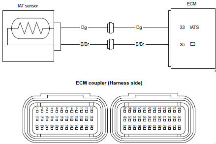
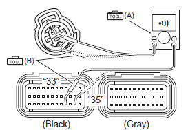
Wiring diagram
Troubleshooting
| Caution when using the multi-circuit tester, do not strongly touch the terminal of the ecm coupler with a needle pointed tester probe to prevent terminal damage. |
| Note after repairing the trouble, clear the dtc using sds tool. Refer to “use of sds diagnosis reset procedures” . |
C21 (use of mode select switch)
|
Step |
Action |
Yes |
No |
|
1 |
Special tool Tester knob indication
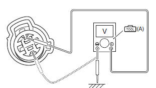
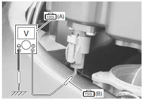
voltage ( Iat sensor input voltage 4.5 – 5.5 V ((+) terminal: dg – (–) terminal: ground, (+) terminal: dg – (–) terminal: b/br)
Is the voltage ok? |
Go to step 2. |
|
 (a): 09900–25008 (multi
 )
)
P0110-h (use of sds)
|
Step |
Action |
Yes |
No |
|
1 |
Special tool Tester knob indication
continuity test ( Ecm couplers (harness side)
Is the continuity ok? |
Connect the ecm coupler and go to step 2. | Dg or b/br wire open. |
 (a): 09900–25008 (multi
 (b): 09900–25009
 )
)
P0110-l (use of sds)
|
Step |
Action |
Yes |
No |
|
|
1 |
Special tool Tester knob indication
continuity test (
Special tool Tester knob indication
voltage ( Iat sensor output voltage 0.15 – 4.85 V ((+) terminal: dg – (–) terminal: ground)
Are the continuity and voltage ok? |
Go to step 2. |
|
|
|
2 |
Special tool Tester knob indication resistance (Ω) Iat sensor resistance approx. 2.58 KΩ at 20 °c (68 °f) (terminal – terminal)
Is the resistance ok? |
|
Replace the iat sensor with a new one. Refer to “iat sensor removal and installation” in section 1c (page 1c- 5). |
 (a): 09900–25008 (multi
 )
)
 )
)
 DTC “c15” (p0115-h/l): ect sensor circuit
malfunction
DTC “c15” (p0115-h/l): ect sensor circuit
malfunction
Detected condition and possible cause
Detected condition
Possible cause
C15
Output voltage is not with in the following
range.
0.15 V ≤ Sensor voltage < ...
 DTC “c22” (p1450-h/l): ap sensor circuit
malfunction
DTC “c22” (p1450-h/l): ap sensor circuit
malfunction
Detected condition and possible cause
Detected condition
Possible cause
C22
Ap sensor voltage is not within the
following range.
0.5 V ≤ Sensor voltage < ...
Other materials:
Tire condition and type
Tire condition and tire type affect
motorcycle performance. Cuts or
cracks in the tires can lead to tire
failure and loss of motorcycle
control. Worn tires are susceptible
to puncture failures and subsequent
loss of motorcycle control.
Tire wear also affects the tire profile,
changing moto ...
Tp sensor adjustment
Inspect the tp sensor setting position and adjust it if
necessary in the following procedures:
connect the special tool (mode select switch) to the dealer mode
coupler. Refer to “self-diagnostic procedures” in section 1a .
Special tool
: 09930–82720 (mode selection switch)
Warn ...
Charging system symptom diagnosis
Condition
Possible cause
Correction / reference item
Generator does not
charge
Open- or short-circuited lead wires, or
loose lead connections.
Repair, replace or connect properly.
Short-circuited, grounded or open
generator coil.
Replace
...