Suzuki GSX-R 1000 Service Manual: DTC “c15” (p0115-h/l): ect sensor circuit malfunction
Detected condition and possible cause
|
Detected condition |
Possible cause |
||
| C15 | Output voltage is not with in the following
range.
0.15 V ≤ Sensor voltage < 4.85 V |
|
|
| P0115 | H | Sensor voltage is higher than specified value. | |
| L | Sensor voltage is lower than specified value. | ||
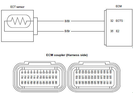
Wiring diagram
Troubleshooting
| Caution when using the multi-circuit tester, do not strongly touch the terminal of the ecm coupler with a needle pointed tester probe to prevent terminal damage. |
| Note after repairing the trouble, clear the dtc using sds tool. Refer to “use of sds diagnosis reset procedures” . |
C15 (use of mode select switch)
|
Step |
Action |
Yes |
No |
|
1 |
Special tool Tester knob indication
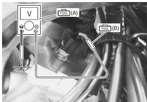
voltage ( Ect sensor input voltage 4.5 – 5.5 V ((+) terminal: b/bl – (–) terminal: ground, (+) terminal: b/bl – (–) terminal: b/br)
Is the voltage ok? |
Go to step 2. |
|
 (a): 09900–25008 (multi
 )
)
P0115-h (use of sds)
|
Step |
Action |
Yes |
No |
|
1 |
Special tool Tester knob indication
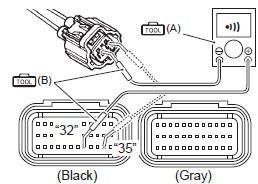
continuity test ( Ecm couplers (harness side)
Is the continuity ok? |
Go to step 2. | B/bl or b/br wire open. |
 )
)
P0115-l (use of sds)
|
Step |
Action |
Yes |
No |
|
|
1 |
Special tool Tester knob indication
continuity test (
Special tool Tester knob indication
voltage ( Ect sensor output voltage 0.15 – 4.85 V ((+) terminal: b/bl – (–) terminal: ground)
Are the continuity and voltage ok? |
Go to step 2. |
|
|
|
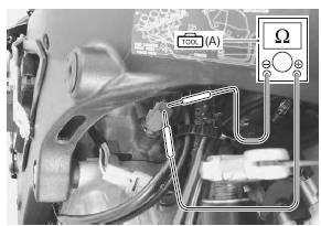
2 |
Special tool Tester knob indication resistance (Ω) Ect sensor resistance approx. 2.45 KΩ at 20 °c (68 °f) (terminal – terminal)
Is the resistance ok? |
|
Replace the ect
sensor with a new one. Refer to “ect sensor removal and installation” in section 1c . |
 (a): 09900–25008 (multi
 )
)
 )
)
 DTC “c14” (p0120-h/l): tp sensor circuit
malfunction
DTC “c14” (p0120-h/l): tp sensor circuit
malfunction
Detected condition and possible cause
Detected condition
Possible cause
C14
Output voltage is not within the following
range.
Difference between actual throttle op ...
 DTC “c21” (p0110-h/l): iat sensor circuit
malfunction
DTC “c21” (p0110-h/l): iat sensor circuit
malfunction
Detected condition and possible cause
Detected condition
Possible cause
C21
Output voltage is not with in the following
range.
0.15 V ≤ Sensor voltage < ...
Other materials:
If you don't have a helmet, buy a helmet and wear it every
time you ride
Most accidents occur within a few
miles of home, and almost half
occur at speeds of less than 30
mph. So even if you're just going
on a quick errand, be preparedstrap
on your helmet before you
take off.
Helmets do not reduce essential
vision or hearing. Generally, helmets
do not cause or ...
Lubrication points
Proper lubrication is important for
smooth operation and long life of
each working part of your motorcycle
and also for safe riding. It is
a good practice to lubricate the
motorcycle after a long rough ride
and after getting it wet it in the
rain or after washing it. Major
lubrication points ...
Precautions
Precautions for engine electrical device
Refer to “general precautions” in section 00 (page 00-1) and “precautions for
electrical circuit service” in section 00
(page 00-2).
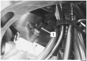
Component location
Engine electrical components location
Refer to “electrical components location” in section 0a .
Dia ...