Suzuki GSX-R 1000 Service Manual: DTC “c14” (p0120-h/l): tp sensor circuit malfunction
Detected condition and possible cause
|
Detected condition |
Possible cause |
||
| C14 | Output voltage is not within the following
range. Difference between actual throttle opening and opening calculated by ecm is larger than specified value. 0.2 V ≤ Sensor voltage < 4.8 V |
|
|
| P0120 | H | Sensor voltage is higher than specified value. |
|
| L | Sensor voltage is lower than specified value. | ||
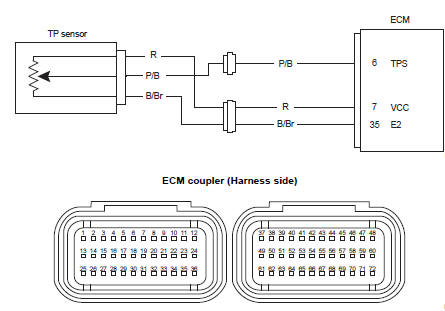
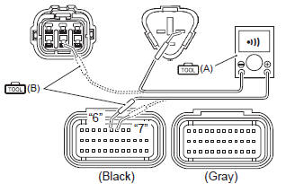
Wiring diagram
Troubleshooting
| Caution when using the multi-circuit tester, do not strongly touch the terminal of the ecm coupler with a needle pointed tester probe to prevent terminal damage. |
| Note after repairing the trouble, clear the dtc using sds tool. Refer to “use of sds diagnosis reset procedures” . |
C14 (use of mode select switch)
|
Step |
Action |
Yes |
No |
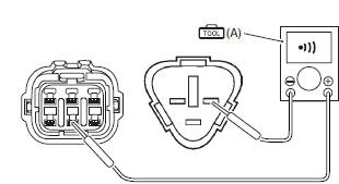
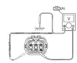
| 1 |
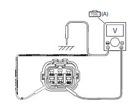
Special tool
Tester knob indication
voltage ( Tp sensor input voltage 4.5 – 5.5 V ((+) terminal: r – (–) terminal: ground, (+) terminal: r – (–) terminal: b/br)
Is the voltage ok? |
Go to step 3. |
|
 (a): 09900–25008 (multi
 )
)
P0120-h (use of sds)
|
Step |
Action |
Yes |
No |
|
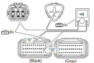
1 |
Special tool Tester knob indication
continuity (
Special tool Tester knob indication continuity test ( ) Ecm couplers (harness side)
Is the continuity ok? |
Go to step 3. | P/b wire shorted to vcc, or b/br wire open |
 (a): 09900–25008 (multi
 )
)
P0120-l (use of sds)
|
Step |
Action |
Yes |
No |
|
1 |
Special tool Tester knob indication
continuity test (
Special tool Tester knob indication
continuity test ( Ecm couplers (harness side)
Is the continuity ok? |
Go to step 2. | R or p/b wire open, or y/w wire shorted to ground. |
|
2 |
Special tool Tester knob indication
voltage ( Tp sensor input voltage 4.5 – 5.5 V ((+) terminal: r – (–) terminal: ground, (+) terminal: r – (–) terminal: b/br)
Is the voltage ok? |
Go to step 3. | Open or short circuit in the r or b/br wire. |
|
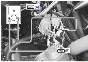
3 |
Special tool Tester knob indication
voltage ( Tp sensor output voltage throttle valve is closed: approx. 1.1 V throttle valve is opened: approx. 4.4 V ((+) terminal: p/b – (–) terminal: b/br)
Is the voltage ok? |
|
If check result is not
satisfactory, replace tp
sensor with a new one. Refer to “throttle body disassembly and assembly” in section 1d . |
 )
)
 )
)
 DTC “c13” (p0105-h/l): iap sensor circuit
malfunction
DTC “c13” (p0105-h/l): iap sensor circuit
malfunction
Detected condition and possible cause
Detected condition
Possible cause
C13
Iap sensor voltage is not within the
following range.
0.5 V ≤ Sensor voltage &l ...
 DTC “c15” (p0115-h/l): ect sensor circuit
malfunction
DTC “c15” (p0115-h/l): ect sensor circuit
malfunction
Detected condition and possible cause
Detected condition
Possible cause
C15
Output voltage is not with in the following
range.
0.15 V ≤ Sensor voltage < ...
Other materials:
Water pump construction
Impeller
Mechanical seal
Oil seal
O-ring
O-ring
8
N·m (0.8 Kgf-m, 6.0 Lbf-ft)
10 N·m
(1.0 Kgf-m, 7.0 Lbf-ft)
Apply grease.
Apply engine coolant.
Apply molybdenum oil
solution.
Do not reuse.
...
Clutch control system components
Push rod
Clutch release camshaft
Clutch release arm
Clutch cable
1 N·m (0.1 Kgf-m, 0.7
Lbf-ft)
6 N·m
(0.6 Kgf-m, 4.5 Lbf-ft)
10 N·m
(1.0 Kgf-m, 0.7 Lbf-ft)
Apply grease
Do not reuse.
...
Rod guide case tightening torque
Tighten the rod guide case in the following procedures:
measure the effective length l of the torque wrench.
Calculate the reading torque on the torque wrench by
use of the formula shown below.
Special tool
(a): 09940–84710 (rod guide case
wrench)
T: reading torque on the torq ...