Suzuki GSX-R 1000 Service Manual: DTC “c12” (p0335): ckp sensor circuit malfunction.
Detected condition and possible cause
|
Detected condition |
Possible cause |
| The signal does not reach ecm for 3 sec. Or more, after receiving the starter signal. |
|
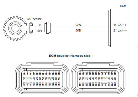
Wiring diagram
Troubleshooting
| Caution when using the multi-circuit tester, do not strongly touch the terminal of the ecm coupler with a needle pointed tester probe to prevent terminal damage. |
| Note after repairing the trouble, clear the dtc using sds tool. Refer to “use of sds diagnosis reset procedures” . |
|
Step |
Action |
Yes |
No |
|
1 |
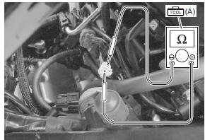
Special tool (a): 09900–25008 (multi circuit tester set) Tester knob indication resistance (Ω) Ckp sensor resistance 142 – 194 Ω (b – bl/y)
Special tool
Ckp sensor continuity ∞Ω¶ (infinity) (b . Ground, bl/y. Ground)
Are the resistance and continuity ok? |
Go to step 2. | Replace the ckp sensor with a new one. |
|
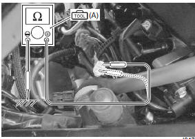
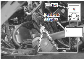
2 |
Special tool
Tester knob indication
voltage ( Ckp sensor peak voltage 0.5 V and more ((+) terminal: b – (–) terminal: bl/y)
Is the voltage ok? |
|
|
 (a): 09900–25008 (multi
 (a): 09900–25008 (multi
 )
)
 DTC “c11” (p0340): cmp sensor circuit
malfunction
DTC “c11” (p0340): cmp sensor circuit
malfunction
Detected condition and possible cause
Detected condition
Possible cause
The signal does not reach ecm for 3 sec. Or more, after
receiving the starter signal.
...
 DTC “c13” (p0105-h/l): iap sensor circuit
malfunction
DTC “c13” (p0105-h/l): iap sensor circuit
malfunction
Detected condition and possible cause
Detected condition
Possible cause
C13
Iap sensor voltage is not within the
following range.
0.5 V ≤ Sensor voltage &l ...
Other materials:
Tp reset
When replacing the throttle body assembly or tp sensor
with a new one or reinstalling the tp sensor, reset the
tp learned value in the following procedures:
Note
keep the throttle valves fully closed while
resetting the tp learned value.
Turn the ignition switch on.
...
Rear brake caliper removal and installation
Removal
Remove the rear wheel. Refer to “rear wheel assembly removal and
installation” in section 2d .
Drain brake fluid. Refer to “brake fluid replacement” in section 4a .
Remove the brake hose from the caliper by
removing the union bolt (1) and catch the brake fluid
in a ...
Be extra safety-conscious on bad weather days
Riding on bad weather days,
especially wet ones, requires
extra caution. Braking distances
increase on a rainy day. Stay off
the painted surface marks, manhole
covers, and greasy-appearing
areas, as they can be
especially slippery. Use extra caution
at railway crossings and on
metal grating ...