Suzuki GSX-R 1000 Service Manual: Water pump disassembly and assembly
Refer to “water pump removal and installation” .
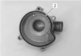
Disassembly
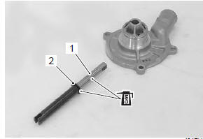
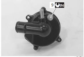
- Remove the air bleeder bolt (1) if necessary.
- Remove the water pump case screws.
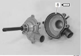
- Remove the o-ring (2).
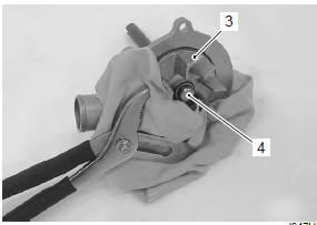
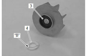
- Hold the impeller (3) with water pump pliers and remove the impeller securing bolt (4).
- Remove the impeller (3).
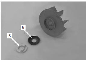
- Remove the mechanical seal ring (5) and rubber seal (6) from the impeller.
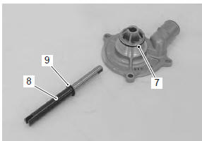
- Remove the o-ring (7), impeller shaft (8) and washer (9) from the holder.
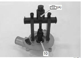
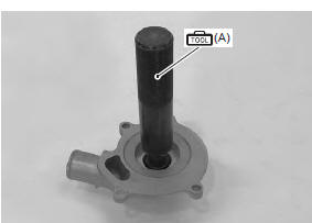
- Remove the mechanical seal (10) with the special tool.
| Note if there is no abnormal condition, the mechanical seal removal is not necessary. |
Special tool
 (a): 09921–20240 (bearing remover
set)
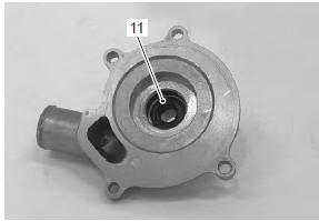
- Remove the oil seal (11).
| Note if there is no abnormal condition, the oil seal removal is not necessary. |
Assembly
- Install the oil seal with the special tool.
| Caution the removed oil seal must be replaced with a new one. |
| Note the stamped mark on the oil seal should face mechanical seal side. |
Special tool
 (a): 09913–70210 (bearing
installing set (10
– 75 ö))
- Apply a small quantity of the grease to the oil seal lip.
 : Grease 99000–25010 (suzuki
super
grease “a” or equivalent)
- Install a new mechanical seal using a suitable size socket wrench.
| Caution the removed mechanical seal must be replaced with a new one. |
| Note on new mechanical seals, the sealer “a” has been applied. |
- Apply molybdenum solution to the impeller shaft (1) and washer (2).
M/o: molybdenum oil (molybdenum oil solution)
- Install the impeller shaft (1) and washer (2) to the holder.
- Install the rubber seal (3) into the impeller.
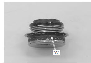
- After wiping off the oily or greasy matter from the mechanical seal ring (4), install it into the impeller.
| Note the paint marked side “b” of mechanical seal ring faces the rubber seal. |
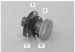
- Install the washer (5) and seal washer (6) onto the impeller securing bolt.
| Note the metal side “c” of seal washer and the curved side “d” of washer face the impeller securing bolt head. |
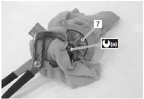
- Install the impeller (7).
- Hold the impeller with water pump pliers and tighten the impeller securing bolt to the specified torque.
Tightening torque impeller securing bolt (a): 8 n·m (0.8 Kgf-m, 6.0 Lbf-ft)
- Install new o-ring (8) and apply engine coolant to it.
| Caution use a new o-ring to prevent engine coolant leakage. |
- Tighten the water pump case screws to the specified torque.
Tightening torque water pump case screw: 6 n·m (0.6 Kgf-m, 4.5 Lbf-ft)
- Tighten the water pump air bleeder bolt (9) to the specified torque.
| Caution use a new gasket washer to prevent engine coolant leakage. |
Tightening torque water pump air bleeder bolt (b): 13 n·m (1.3 Kgfm, 9.5 Lbf-ft)
 Water pump removal and installation
Removal
Note
before draining engine oil and engine coolant, inspect engine oil and
coolant leakage between the water pump and crankcase. If engine oil is
leaking, visually inspect t ...
 Water pump related parts inspection
Refer to “water pump disassembly and assembly” .
Mechanical seal
Visually inspect the mechanical seal for damage, with
particular attention given to the sealing face.
Replace the mechanical seal ...
Other materials:
Excva removal and installation
Removal
Turn the ignition switch off.
Remove the left side cowling. Refer to “exterior parts removal and
installation” in section 9d .
Connect the special tool (mode select switch) to the dealer mode
coupler. Refer to “self-diagnostic procedures” in section 1a .
After tur ...
Specifications
Tightening torque specifications
Note
the specified tightening torque is described in the following.
“Rear view mirror construction”
Reference: for the tightening torque of fastener not specified in this
section, refer to “tightening torque list” in section 0c . ...
Special tools and equipment
Recommended service material
Note
required service material is also described in the following.
“Lubrication points”
Special tool
...