Suzuki GSX-R 1000 Service Manual: Front wheel related parts inspection
Refer to “front wheel assembly removal and installation” .
Tire
Refer to “tire inspection” in section 0b .
Front brake disc
Refer to “front brake disc inspection” in section 4b .
Dust seal
Inspect the lip of dust seals for wear or damage. If any defects are found, replace the dust seal with a new one.
Refer to “front wheel dust seal / bearing removal and installation” .
Wheel axle
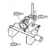
Using a dial gauge, check the wheel axle for runout. If the runout exceeds the limit, replace the axle shaft.
Special tool (a): 09900–20607 (dial gauge) (b): 09900–20701 (dial gauge chuck) (c): 09900–21304 (v blocks)
Wheel axle runout service limit: 0.25 Mm (0.010 In)
Wheel
- Remove the brake pads. Refer to “front brake pad replacement” in section 4b .
- Make sure that the wheel runout checked as shown in the figure does not exceed the service limit. An excessive runout is usually due to worn or loosened wheel bearings and can be reduced by replacing the bearings. If bearing replacement fails to reduce the runout, replace the wheel.
Wheel rim runout service limit (axial and radial): 2.0 Mm (0.08 In)
- Install the brake pads. Refer to “front brake pad replacement” in section 4b .
Wheel bearing
Inspect the play of the wheel bearings by finger while they are in the wheel. Rotate the inner race by finger to inspect for abnormal noise and smooth rotation. Replace the bearing if there is anything unusual. Refer to “front wheel dust seal / bearing removal and installation” .
 Front wheel assembly removal and installation
Removal
Remove the brake calipers, left and right.
Caution
do not operate the brake lever with the
caliper removed.
Loosen two axle pinch bolts (1) on the right front ...
 Front wheel dust seal / bearing removal and installation
Removal
Remove the front wheel assembly. Refer to “front wheel assembly removal
and installation” .
Remove the dust seals using the special tool.
Special tool
(a): 09913–50121 (oil ...
Other materials:
Rear brake pad replacement
Remove the plug (1) and brake pad mounting pin (2).
Remove the brake pads (3).
Caution
do not operate the brake pedal while the
pads are removed.
Clean up the caliper, especially around the caliper
piston.
Caution
replace the brake pads as a s ...
Exhaust emission control system
description
The exhaust emission control system is composed of the pair system, exhaust
control system, ho2 sensor, threeway
catalyst system and isc system. The fresh air is drawn into the exhaust ports
through the pair control solenoid
valve and pair reed valves. The pair control solenoid valve is operat ...
Specifications
Service data
Electrical
Tightening torque specifications
Note
the specified tightening torque is described in the following.
“Wiring harness routing diagram”
Reference: for the tightening torque of fastener not specified in this
section, refer to “tightening torque l ...