Suzuki GSX-R 1000 Service Manual: Schematic and routing diagram
Ignition system diagram
Refer to “wire color symbols” in section 0a .
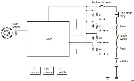
Ignition system components location
Refer to “electrical components location” in section 0a .
 Drive mode selector description
Engine power characteristics can be changed in 3
modes by operating the drive mode selector to meet
various riding conditions and rider’s preference.
Operation
Drive mode is preset at a-mode w ...

Other materials:
Throttle valve synchronization
Check and adjust the throttle valve synchronization
among four cylinders.
Start the engine and run it in idling condition
for
warming up.
Stop the warmed-up engine.
Lift and support the fuel tank. Refer to “fuel
tank
removal and installation” in section 1g (page ...
Front suspension adjustment
After installing the front fork, adjust the spring pre-load
and two kinds of damping force as follows:
Adjust the
left and right front forks to the
same setting.
Spring pre-load adjustment
Turn the spring pre-load adjuster (1) counterclockwise
fully. From that position (softe ...
Dimmer / passing light switch inspection
Inspect the dimmer/passing light switch in the following
procedures:
remove the air cleaner box. Refer to “air cleaner box removal and
installation” in section 1d .
Disconnect the left handlebar switch coupler (1).
(Yellow)
Inspect the dimmer/passing light switch ...