Suzuki GSX-R 1000 Service Manual: Schematic and routing diagram
Refer to “wire color symbols” in section 0a .
Component location
Starting system components location
Refer to “electrical components location” in section 0a .
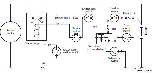
 Starting system
...
 Diagnostic information and procedures
Starting system symptom diagnosis
Condition
Possible cause
Correction / reference item
Engine does not turn
though the starter motor
runs
Faulty starter clu ...
Other materials:
DTC “c40” (p0505 / p0506 / p0507): isc
valve circuit malfunction
Detected condition and possible cause
Detected condition
Possible cause
C40/P0505
The circuit voltage of motor drive is
unusual.
Isc valve circuit open or shorted to ground.
Air passage clogged.
Isc valve is fixed.
Isc valve prese ...
Dimmer / passing light switch inspection
Inspect the dimmer/passing light switch in the following
procedures:
remove the air cleaner box. Refer to “air cleaner box removal and
installation” in section 1d .
Disconnect the left handlebar switch coupler (1).
(Yellow)
Inspect the dimmer/passing light switch ...
Special tools and equipment
Special tool
...