Suzuki GSX-R 1000 Service Manual: Camshaft inspection
Refer to “engine top side disassembly” .
Refer to “engine top side assembly” .
Camshaft identification
The exhaust camshaft has the embossed letters “ex” and the intake camshaft has the embossed letters “in”.

Cam wear
Check the camshaft for wear or damage.
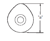
Measure the cam height “a” with a micrometer.
Replace a camshaft if the cams are worn to the service limit.
Special tool
 : 09900–20202 (micrometer (25 – 50
mm))
Cam height “a” service limit (in.): 37.38 Mm (1.472 In) service limit (ex.): 36.58 Mm (1.440 In)

Camshaft runout
Measure the runout using the dial gauge. Replace the camshaft if the runout exceeds the limit.
Special tool
 (a): 09900–20607 (dial gauge)
 (b): 09900–20701 (dial gauge chuck)
 (c): 09900–21304 (v blocks)
Camshaft runout (in. & Ex.) Service limit: 0.10 Mm (0.004 In)

Camshaft journal wear
Inspect the camshaft journal wear in the following procedures:
- determine whether or not each journal is worn down to the limit by measuring the oil clearance with the camshaft installed in place.
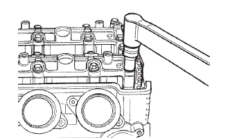
- Use the plastigauge to read the clearance at the widest portion, which is specified as follows.
Special tool

(a):
09900–22301 (plastigage (0.025 – 0.076
Mm))

(b):
09900–22302 (plastigage (0.051 – 0.152
Mm))

- Install each camshaft journal holder to its original position. Refer to “engine top side assembly” .
- Tighten the camshaft journal holder bolts in
ascending order of numbers to the specified torque.
Refer to “engine top side assembly” .
| Note do not rotate the camshafts with the plastigauge in place. |
Tightening torque camshaft journal holder bolt: 10 n·m (1.0 Kgfm, 7.0 Lbf-ft)

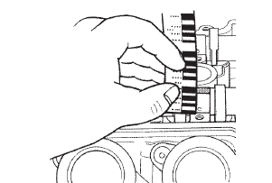
- Remove the camshaft journal holders and measure the width of the compressed plastigauge using the envelope scale.
- This measurement should be taken at the widest part of the compressed plastigauge.
Camshaft journal oil clearance (in. & Ex.) Service limit: 0.150 Mm (0.0059 In)

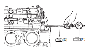
- If the camshaft journal oil clearance exceeds the limit, measure the inside diameter of the camshaft journal holder and the outside diameter of the camshaft journal. Replace the camshaft or the cylinder head depending upon which one exceeds the specification.
Special tool
 (c): 09900–20602 (dial gauge)
 (d): 09900–22403 (small bore gauge
(18 –
35 mm))
 (e): 09900–20205 (micrometer (0 – 25
mm))
Camshaft journal holder i.D. (In. & Ex.) Standard: 24.012 – 24.025 Mm (0.9454 – 0.9459 In)
Camshaft journal o.D. (In. & Ex.) Standard: 23.959 – 23.980 Mm (0.9433 – 0.9441 In)


 Cylinder head cover related parts
inspection
Refer to “engine top side disassembly” .
Refer to “engine top side assembly” .
Refer to “cylinder head cover disassembly and assembly” .
Cylinder head cover
Clean and check the gasket grooves ...
 Camshaft sprocket
Inspect the camshaft sprocket in the following
procedures:
remove the intake and exhaust camshafts. Refer to “engine top side
disassembly” .
Inspect the teeth of each camshaft sp ...
Other materials:
Special tools and equipment
Recommended service material
Note
required service material is also described in the following.
“Lubrication points”
Special tool
...
Clutch parts inspection
Refer to “clutch removal” and “clutch installation” .
Clutch drive and driven plate
Note
wipe off the engine oil from the drive and
driven plates with a clean rag.
Measure the thickness of drive plates with a vernier
calipers. If the drive plate thickness is found to have ...
Sprocket mounting drum dust seal / bearing removal and installation
Removal
Remove the rear wheel assembly. Refer to “rear wheel assembly removal
and installation” in section 2d .
Remove the rear sprocket mounting drum assembly
(1). Refer to “rear sprocket / rear sprocket
mounting drum removal and installation” (page 3a-
3).
Remove the ...
