Suzuki GSX-R 1000 Service Manual: Component location
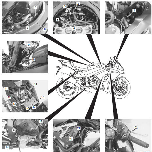
Electrical components location
|
 Country and area codes
The following codes stand for the applicable country(-ies) and area(-s).
Wire color symbols
Warning, caution and information labels location
Noise label
Information ...
 Specifications
Specifications
Note
these specifications are subject to change without notice.
Dimensions and dry mass
Engine
Drive train
Chassis
Electrical
Capacities
...
Other materials:
Rear suspension assembly construction
Rear shock absorber mounting bolt (upper)
Rear shock absorber mounting nut (lower)
Cushion rod mounting nut (front)
Cushion rod mounting nut (rear)
Cushion lever mounting nut
Swingarm pivot nut
Swingarm pivot boss nut
Swingarm pivot shaft
Swingarm ...
Clutch installation
Install the primary driven gear assembly (1).
Caution
if it is difficult to install the primary driven
gear, rotate the crankshaft.
Be sure to engage the oil pump drive
sprocket with the primary driven gear.
Install the spacer (2) and bea ...
Precautions
Precautions for suspension
Refer to “general precautions” in section 00 (page 00-1).
All
suspensions, bolts and nuts are an important part in that it could
affect the performance of vital
parts. They must be tightened to the specified torque periodically and
if the suspension ...