Suzuki GSX-R 1000 Service Manual: Component location
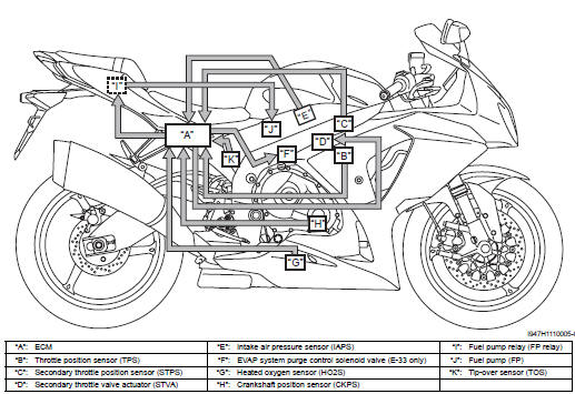
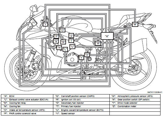
Fi system parts location
 Schematic and routing diagram
FI system wiring diagram
Terminal alignment of ecm coupler
...

Other materials:
Rear turn signal light removal and installation
Removal
Remove the frame cover assembly. Refer to “exterior parts removal and
installation” in section 9d .
Remove the rear combination light. Refer to “rear combination light
removal and installation” .
Disconnect the lead wire coupler (1).
(Lh: white, rh: black)
&nb ...
Specifications
Service data
Oil pump
Oil
Tightening torque specifications
Reference: for the tightening torque of fastener not specified in this
section, refer to “tightening torque list” in section 0c . ...
Steering components
Steering stem head nut
Steering stem upper bracket
Steering stem lock-nut
Washer
Steering stem nut
Dust seal cover
Dust seal
Steering stem upper bearing
Steering stem lower bearing
Lower seal
Steering stem lower bracket
Steering stem lo ...