Suzuki GSX-R 1000 Service Manual: Schematic and routing diagram
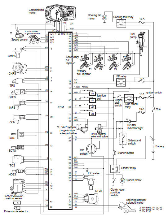
FI system wiring diagram
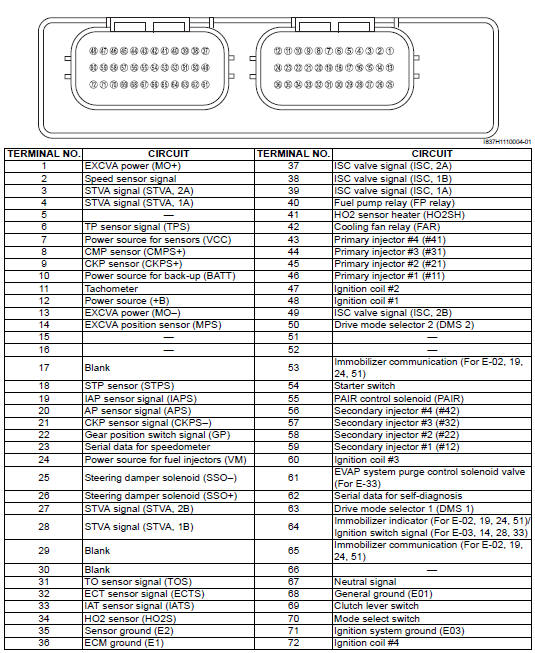
Terminal alignment of ecm coupler
 Self-diagnosis function
The self-diagnosis function is incorporated in the ecm. The function has two
modes, “user mode” and “dealer mode”.
The user can only be notified by the lcd (display) panel and led (fi indicator
...
 Component location
Fi system parts location
...
Other materials:
Engine top side disassembly
It is unnecessary to remove the engine assembly from
the frame when servicing the cylinder head cover and
camshafts.
Note
before servicing the engine top side
components (until camshafts removal) with
the engine in place, remove the following
parts:
air cleaner box
...
Cylinder inspection
Refer to “engine top side disassembly” .
Refer to “engine top side assembly” .
Cylinder distortion
Check the gasket surface of the cylinder for distortion.
Use a straightedge and thickness gauge. Take clearance
readings at several places. If any reading exceeds the
service limit, replace t ...
Damping force adjustment
The rebound and compression
damping force can be individually
adjusted by turning the respective
adjusters. The rebound damping
force adjuster 2 is located at the
top of the front fork. The compression
damping force adjuster 3 is
located at the bottom of the front
fork.
To adjust the da ...