Suzuki GSX-R 1000 Service Manual: Self-diagnosis function
The self-diagnosis function is incorporated in the ecm. The function has two modes, “user mode” and “dealer mode”.
The user can only be notified by the lcd (display) panel and led (fi indicator light). To check the function of the individual fi system devices, the dealer mode is provided. In this check, the special tool is necessary to read the code of the malfunction items.
User mode
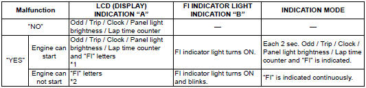
*1
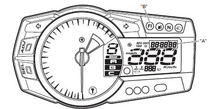
When one of the signals is not received by ecm, the fail-safe circuit works and injection is not stopped. In this case, “fi” and odd / trip / clock / panel light brightness / lap time counter are indicated in the lcd panel and motorcycle can run.
*2
The injection signal is stopped, when the camshaft position sensor signal, crankshaft position sensor signal, tip-over sensor signal, #1, #2, #3 and #4 ignition signals, #1, #2, #3 and #4 injector signals, fuel pump relay signal or ignition switch signal is not sent to ecm. In this case, “fi” is indicated in the lcd panel. Motorcycle does not run.
“Chec”:
the lcd panel indicates “chec” when no communication signal from the ecm is received for 5 seconds.
For example:
the ignition switch is turned on, and the engine stop switch is turned off. In this case, the speedometer does not receive any signal from ecm, and the panel indicates “chec”. If chec is indicated, the lcd does not indicate the trouble code. It is necessary to check the wiring harness between ecm and speedometer couplers.The possible cause of this indication is as follows: engine stop switch is in off position. Side-stand/ignition inter-lock system is not working. Ignition fuse is burnt.
“Sd”:
the lcd panel indicates “sd” when the steering damper solenoid malfunction, battery abnormal voltage and speed sensor malfunction occurred.
Dealer mode
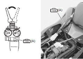
The defective function is memorized in the computer. Use the special tool’s coupler to connect to the mode select switch. The memorized malfunction code is displayed on lcd (display) panel. Malfunction means that the ecm does not receive signal from the devices. These affected devices are indicated in the code form.
 Caution Caution
If the coupler from the ecm is disconnected, the malfunction code memory is erased and the malfunction code can not be checked. |
Special tool
 (a): 09930–82720 (mode selection
switch)

 Injection timing description
Injection time (injection volume)
The factors to determine the injection time include the basic fuel injection
time, which is calculated on the basis of the
intake air pressure, engine speed and t ...
 Schematic and routing diagram
FI system wiring diagram
Terminal alignment of ecm coupler
...
Other materials:
Starter relay removal and installation
Removal
Turn the ignition switch off.
Remove the front seat. Refer to “exterior parts
removal and installation” in section 9d (page 9d-
6).
Disconnect the battery (–) lead wire (1) from the
battery.
Remove the starter relay cover (2) and disconnect
the starter rel ...
Specifications
Specifications
Note
these specifications are subject to change without notice.
Dimensions and dry mass
Engine
Drive train
Chassis
Electrical
Capacities
...
Gearshift lever height inspection and
adjustment
Inspect and adjust the gearshift lever height in the
following procedures:
inspect the gearshift lever height “a” between the
lever top and footrest.
Adjust the gearshift lever height if necessary.
Gearshift lever height “a”
standard: 65 – 75 mm (2.6 – 3.0 In)
Loosen the l ...