Suzuki GSX-R 1000 Service Manual: DTC “c46” (p1657-h/l or p1658): excv
actuator circuit malfunction
|
Detected condition |
Possible cause |
| C46 |
The operation signal does not reach the
excv actuator.
Excva position sensor voltage low or
high
0.14 V ≤ Sensor voltage < 4.9 V
(without the above range)
excva can not operate properly. |
- Excva maladjusted.
- Excva circuit open or short.
- Excva motor malfunction.
- Excva position sensor malfunction.
- Excva position sensor circuit shorted to vcc or ground
circuit open.
- Excva position sensor circuit open or shorted to ground
or vcc circuit open.
- Excva motor circuit open or short.
- Excva motor malfunction.
|
| P1657 |
H |
Sensor voltage is higher than specified
value. |
| L |
Sensor voltage is lower than specified
value. |
| P1658 |
The operation signal does not reach the
excva motor.
Excva can not operate properly. |
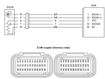
Wiring diagram
Troubleshooting
| Caution
when using the multi-circuit tester, do not strongly touch the terminal
of the ecm coupler with a
needle pointed tester probe to prevent terminal damage. |
| Note
after repairing the trouble, clear the dtc using sds tool. Refer to “use
of sds diagnosis reset procedures” . |
C46 (use of mode select switch)
|
Step |
Action |
Yes |
No |
|
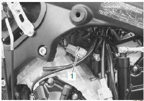
1 |
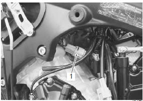
- Turn the ignition switch off.
- Remove the left side cowling. Refer to “exterior parts removal
and installation” in section 9d .
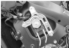
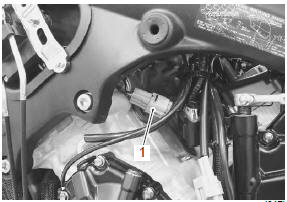
- Check the excva coupler (1) for loose or poor contacts.

- Turn the ignition switch on.
- Check the operation of the excva.
(Excva operation order: full close →
full open →
approx. 80% Open)
Is the operation ok? |
Go to step 2. |
Go to step 6. |
P1657-h (use of sds)
|
Step |
Action |
Yes |
No |
|
1 |
- Turn the ignition switch off.
- Remove the left side cowling. Refer to “exterior parts removal
and installation” in section 9d .
- Check the excva coupler (1) for loose or poor contacts.
If ok, then check the excva position sensor lead wire
continuity.
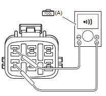
- Disconnect the excva coupler.
- Check the continuity between r wire and y wire.
If the sound is not heard from the tester, the circuit
condition is ok.
Special tool
 (a): 09900–25008 (multi (a): 09900–25008 (multi
circuit tester set)
Tester knob indication
continuity (  ) )
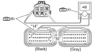
- Disconnect the ecm couplers.
- Check the continuity between y wire and terminal “14”.
- Also, check the continuity between b/br wire and
terminal “35”.
Special tool
 (a): 09900–25008 (multi (a): 09900–25008 (multi
circuit tester set)
 (b): 09900–25009 (b): 09900–25009
(needle-point probe set)
Tester knob indication
continuity (  ) )
Excva lead wire continuity
continuity (  ) )
Ecm couplers (harness side)
Is the continuity ok? |
Go to step 4. |
Y wire shorted to vcc,
or b/br wire open. |
P1657-l (use of sds)
|
Step |
Action |
Yes |
No |
|
1 |
- Turn the ignition switch off.
- Remove the left side cowling. Refer to “exterior parts removal
and installation” in section 9d .
- Check the excva coupler (1) for loose or poor contacts.
If ok, then check the excva position sensor lead wire
continuity.
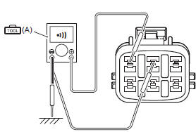
- Disconnect the excva coupler.
- Check the continuity between y wire and ground.
- Also, check the continuity between y wire and b/br wire.
If the sound is not heard from the tester, the circuit
condition is ok.
Special tool
 (a): 09900–25008 (multi (a): 09900–25008 (multi
circuit tester set)
Tester knob indication
voltage ( ) )
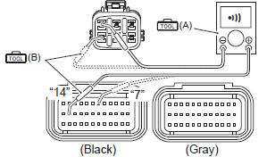
- Disconnect the ecm coupler.
- Check the continuity between y wire and terminal “14”.
- Also, check the continuity between r wire and terminal
“7”.
Special tool
(a): 09900–25008 (multi
circuit tester set)
(b): 09900–25009
(needle-point probe set)
Tester knob indication
continuity ( )
Excva lead wire continuity
continuity ( )
Ecm couplers (harness side)
Is the continuity ok? |
Go to step 2 and go to
step 4. |
R or y wire open, or y
wire shorted to ground. |
P1658 (use of sds)
|
Step |
Action |
Yes |
No |
|
1 |
- Turn the ignition switch off.
- Remove the left side cowling. Refer to “exterior parts removal
and installation” in section 9d .
- Check the excva coupler (1) for loose or poor contacts.
Is the connection ok? |
Go to step 6. |
Loose or poor contacts
on the excva coupler. |
|
2 |
- Turn the ignition switch off.
- Check the installation of excv cables. If it is necessary,
adjust the excv cables. Refer to “excv cable removal and
installation” in section 1k .
- Disconnect the excva coupler (1).
- Turn the ignition switch on.
- Measure the voltage between the r wire and ground.
- If ok, then measure the voltage between the r wire and
b/br wire.
Special tool
 (a): 09900–25008 (multi (a): 09900–25008 (multi
circuit tester set)
Tester knob indication
voltage ( ) )
Excva position sensor input voltage
4.5 – 5.5 V
((+) terminal: r – (–) terminal: ground)
((+) terminal: r – (–) terminal: b/br)
Is the voltage ok? |
Go to step 3. |
- Loose or poor
contacts on the ecm
coupler (terminal “7”
or “35”).
- Open or short circuit
in the r or b/br wire.
|
|
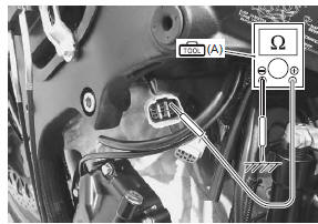
3 |
- Turn the ignition switch off.
- Check the continuity between y wire and ground.
Special tool
 (a): 09900–25008 (multi (a): 09900–25008 (multi
circuit tester set)
Excva position sensor continuity
∞Ω¶ (infinity)
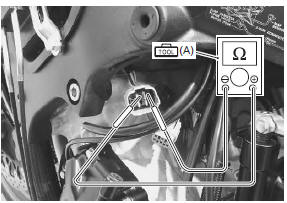
- If ok, then measure the excva position sensor
resistance.
- Connect the excva coupler and set the excva to adjustment
position. Refer to “excv cable removal and installation” in section
1k .
- Disconnect the excva coupler and measure the
resistance between y and w wires.
Special tool
(a): 09900–25008 (multi circuit tester set)
Tester knob indication
resistance (Ω)
Excva position sensor resistance at adjustment
position
approx. 3.1 KΩ
((+) y – (–) w)
Is the resistance ok? |
Go to step 4. |
Replace the excva
with a new one. |
|
4 |
- Turn the ignition switch off.
- Connect the excva coupler.
- Set up the sds tools. Refer to “self-diagnostic procedures” .
- Turn the ignition switch on.
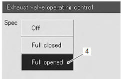
- Click “exhaust valve operating control” (1).
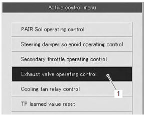
- Click “full closed” (2).
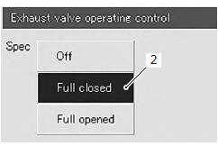
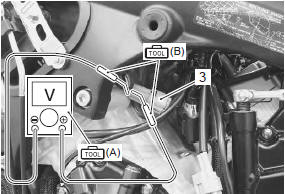
- Insert the needle pointed probes into the back side of the
excva coupler (3). ((+) Y – (–) w)
- measure the excva position sensor output voltage at
excv fully closed position.
Special tool
 (a): 09900–25008 (multi (a): 09900–25008 (multi
circuit tester set)
 (b): 09900–25009 (b): 09900–25009
(needle-point probe set)
Tester knob indication
voltage (  ) )
Excva position sensor output voltage
excv is fully closed: 0.45 – 1.4 V
((+) y – (–) w)
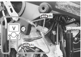
- Click “full opened” (4).
- Measure the excva position sensor output voltage at
excv fully opened position.
Special tool
 (a): 09900–25008 (multi (a): 09900–25008 (multi
circuit tester set)
 (b): 09900–25009 (b): 09900–25009
(needle-point probe set)
Excva position sensor output voltage
excv is fully opened: 3.6 – 4.55 V
((+) y – (–) w)
Is the voltage ok? |
Replace the ecm with a
known good one, and
inspect it again. |
Go to step 5. |
|
5 |
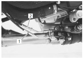
- If the excva position sensor output voltage is 0.45 V and less
at excv fully closed position, adjust the output voltage to the
specified value by turning the no. 1 Cable adjuster (1). Refer to
“excv cable removal and installation” in section 1k .
- Repeat the procedure in step 4 until the output voltage is
set within the specified value. (If c46/p1657 code is
indicated after adjusting the voltage, increase the
voltage to 0.9 V).
Caution
- adjusting the cable with the excv fully opened or fully
closed can damage the excva. Be sure to adjust the cable
with the excv set in the adjustment position. Refer to “excv
cable removal and installation” in section 1k .
- Do not turn the excva pulley using a wrench.
|
- If the excva position sensor output voltage is 4.55 V and more
at excv fully opened position, adjust the output voltage to the
specified value by turning the no. 2 Cable adjuster (2). Refer to
“excv cable removal and installation” in section 1k . Repeat the
procedure in step 4 until the output voltage is set within
the specified value.
Excva position sensor output voltage
excv is fully closed: 0.45 ≤ Output
voltage ≤ 1.4
Excv is fully opened: 3.6 ≤ Output
voltage ≤ 4.55
Is the voltage ok? |
Replace the ecm with a
known good one, and
inspect it again. |
Replace the excva
with a new one. |
|
6 |
- Turn the ignition switch off.
- Disconnect the excva coupler (1).
- Apply 12 v to the terminals and check the operation of
excva.
- Then, switch the wires supplied 12 v and check the
operation of excva. (Check the operation of excva in
both way.)
Is the operation ok? |
- Loose or poor
contacts on the
excva or ecm
coupler (terminal “13”
or “1”).
- Open or short circuit
in the b/r wire or r/b
wire.
- If wire and
connection are ok,
intermittent trouble or
faulty ecm.
- Recheck each
terminal and wire
harness for open
circuit and poor
connection.
- Replace the ecm
with a known good
one, and inspect it
again.
|
- Replace the excva
with a new one.
- Inspect that the
excv and two cables
move smoothly.
|
Detected condition and possible cause
Detected condition
Possible cause
C44/P0130
Ho2 sensor output voltage is not input to
ecm during engine operation and running
...
Detected condition and possible cause
Detected condition
Possible cause
Pair control solenoid valve voltage is not input to ecm
Pair control solenoid valve circ ...
Other materials:
Tire inspection
Inspect tire
every 6 000 km (4 000 miles, 12 months)
Tire tread condition
Operating the motorcycle with excessively worn tires will
decrease riding stability and consequently invite a
dangerous situation. It is highly recommended to replace
a tire when the remaining depth of tire tread reaches ...
Balancer shaft disassembly and assembly
Refer to “engine bottom side disassembly” (page 1d-
49).
Refer to “engine bottom side assembly” .
Disassembly
Remove the balancer shaft. Refer to “engine bottom side disassembly” .
Remove the washers, balancer gear and dampers
from the shaft.
Assembly
Assembly is in the re ...
Heated oxygen sensor (ho2s) removal and
installation
Removal
Do not
remove the ho2 sensor while it is hot.
Caution
be careful not to expose the ho2 sensor to
excessive shock.
Do not use an impact wrench when
removing or installing the ho2 sensor.
Be careful not to twist or damage t ...
 DTC “c44” (p0130/p0135): ho2 sensor
(ho2s) circuit malfunction
DTC “c44” (p0130/p0135): ho2 sensor
(ho2s) circuit malfunction DTC “c49” (p1656): pair control solenoid
valve circuit malfunction
DTC “c49” (p1656): pair control solenoid
valve circuit malfunction