Suzuki GSX-R 1000 Service Manual: Throttle body disassembly and assembly
Refer to “throttle body removal and installation” .
Disassembly
| Caution identify the position of each removed part. Organize the parts in their respective groups so that they can be reinstalled in their original positions. |
- Disconnect the fuel feed hose (1), isc valve hose (2) and vacuum hoses (3).
- Disconnect the purge hose (4). (E-33 only)
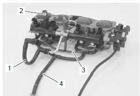
- Remove the fuel delivery pipe assembly (5).
| Caution be careful not to twist the fuel delivery pipes and t-joint (6) when removing them, or joint part “a” of the fuel delivery pipe get damage. |
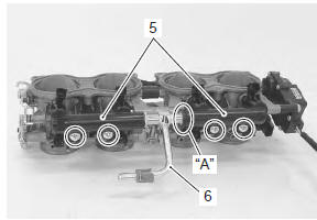
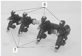
- Remove the primary fuel injectors (7) and secondary fuel injectors (8) from the fuel delivery pipes.
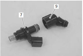
- Remove the fuel pipe (9) from the primary fuel injectors (7).
- Remove the t-joint (6) from the fuel delivery pipes.
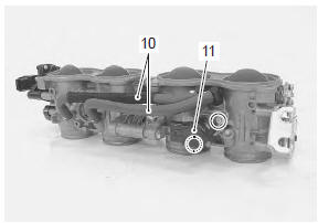
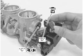
- Remove the isc valve hoses (10) and isc valve (11).
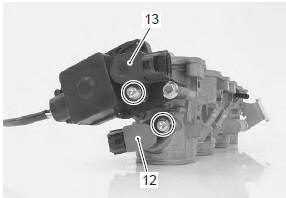
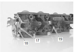
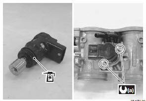
- Remove the tp sensor (12) and stp sensor (13) with the special tool.
Special tool
 : 09930–11950 (torx wrench (5 mm))
| Note prior to disassembly, mark each sensor’s original position with a paint or scribe for accurate reinstallation. |
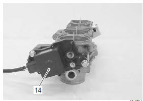
| Caution never remove the stva (14) from the throttle body. |
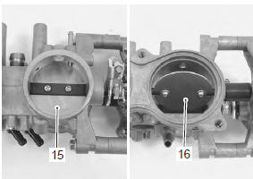
| Caution never remove the throttle valves (15) and secondary throttle valves (16). |
Caution
|
Assembly
Reassemble the throttle body in the reverse order of disassembly. Pay attention to the following points:
- with the secondary throttle valves fully opened, install the stp sensor (black) and tighten the stp sensor mounting screw to the specified torque.
Note
|
 : Grease 99000–25010 (suzuki
super
grease “a” or equivalent)
Special tool
 : 09930–11950 (torx wrench (5 mm))
Tightening torque stp sensor mounting screw: 3.5 N·m (0.35 Kgfm, 2.5 Lbf-ft)
Note
|
- With the throttle valves fully closed, install the tp sensor (gray) and tighten the tp sensor mounting screw to the specified torque.
Caution
|
: Grease 99000–25010 (suzuki
super
grease “a” or equivalent)
Special tool
: 09930–11950 (torx wrench (5 mm))
Tightening torque tp sensor mounting screw: 3.5 N·m (0.35 Kgf-m, 2.5 Lbf-ft)
Note
|
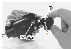
- Apply a thin coat of engine oil to the o-ring, install the isc valve to the throttle body and tighten the isc valve mounting screw to the specified torque.
Special tool
: 09930–11960 (torx wrench (4 mm))
Tightening torque isc valve mounting screw (a): 2 n·m (0.2 Kgf-m, 1.5 Lbf-ft)
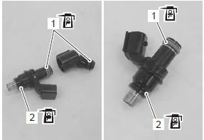
- Apply thin coat of engine oil to the new o-rings (1) and cushion seals (2).
| Caution replace the o-rings and cushion seals with new ones. |
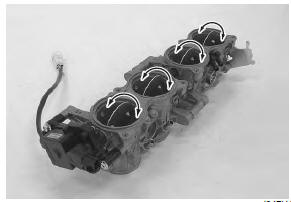
- Assemble the fuel delivery pipes so the t-joint is set in proper angle as shown in the figure.
| Caution be careful not to twist the fuel delivery pipes and t-joint when installing them, or joint part “e” of the fuel delivery pipe may get damage. |
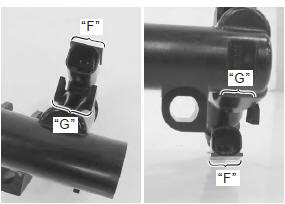
- Install each fuel injector by pushing it straight to the delivery pipe.
| Caution never turn the injector while pushing it. |
| Note align the coupler “f” of injector with boss “g” of the delivery pipe. |
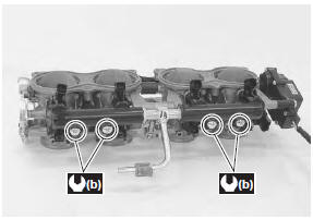
- Install the fuel delivery pipe assembly to the throttle body.
- Tighten the fuel delivery pipe mounting screws to the specified torque.
Tightening torque fuel delivery pipe mounting screw (b): 3.5 N·m ( 0.35 Kgf-m, 2.5 Lbf-ft)
Connect the hoses properly. Refer to “throttle body construction” .
 Throttle body removal and installation
Removal
Remove the side cowlings. Refer to “exterior parts
removal and installation” in section 9d (page 9d-
6).
Remove the air cleaner box. Refer to “air cleaner box removal and
in ...
 Throttle body inspection and cleaning
Refer to “throttle body disassembly and assembly” .
Cleaning
Some
carburetor cleaning chemicals,
especially dip-type soaking solutions, are
very corrosive and must be handled carefu ...
Other materials:
Front wheel related parts inspection
Refer to “front wheel assembly removal and installation” .
Tire
Refer to “tire inspection” in section 0b .
Front brake disc
Refer to “front brake disc inspection” in section 4b .
Dust seal
Inspect the lip of dust seals for wear or damage. If any
defects are found, replace the dust seal ...
License plate light removal and installation
Removal
Remove the frame cover. Refer to “exterior parts
removal and installation” in section 9d (page 9d-
6).
Disconnect the license plate light coupler (1).
Remove the nuts.
Remove the license plate light assembly (2).
Installation
Install the license pl ...
Front brake caliper parts inspection
Refer to “front brake caliper disassembly and assembly” .
Brake caliper cylinder
Inspect the brake caliper cylinder wall for nicks,
scratches or other damage. If any damage is found,
replace the caliper with a new one.
Brake caliper piston
Inspect the surface of brake caliper pistons for a ...