Suzuki GSX-R 1000 Service Manual: Throttle body removal and installation
Removal
- Remove the side cowlings. Refer to “exterior parts removal and installation” in section 9d (page 9d- 6).
- Remove the air cleaner box. Refer to “air cleaner box removal and installation” .
- Remove the clamps (1).
- Disconnect the iap sensor (2) from the vacuum hose.
- Disconnect the stva lead wire coupler (3).
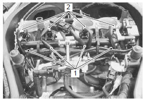
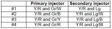
- Disconnect secondary fuel injector couplers (4) and primary fuel injector couplers (5).
- Disconnect the purge hose (6) from the evap system purge control solenoid valve. (E-33 only)
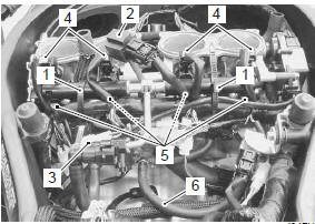
- Remove the clamp (7).
- Disconnect the isc valve coupler (8).
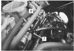
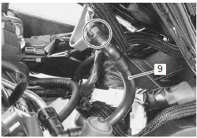
- Place a rag under the fuel feed hose (9) and disconnect the fuel feed hose from the fuel pump.
 For e-33 For e-33
models, drain fuel from the fuel tank before disconnecting the fuel feed hose to prevent fuel leakage. |
- Loosen the throttle body clamp screws, left and right.
- Lift up the throttle body from the intake pipes.
- Disconnect the stp sensor coupler (10) and tp sensor coupler (11).
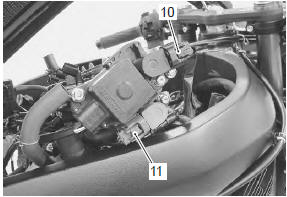
- Disconnect the throttle cables.
| Caution after disconnecting the throttle cables, do not snap the throttle valve from full open to full close. It may cause damage to the throttle valve and throttle body. |
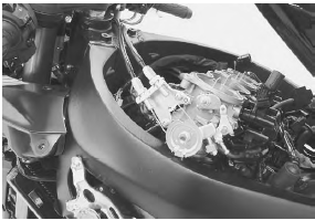
- Remove the throttle body.
Installation
Installation is in the reverse order of removal. Pay attention to the following points:
- connect the primary injector couplers (1) and secondary injector couplers (2) to the respective fuel injectors. Make sure that each coupler is installed in the correct position. The color on each lead wire refers to the appropriate fuel injector.
- Connect the throttle cable no. 1 (3) And throttle cable no. 2 (4) To the throttle cable drum.
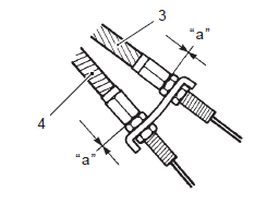
|
- Loosen each throttle cable lock-nut.
- Turn in each throttle cable adjuster fully and locate each outer cable so that the clearance “a” is 0 – 1 mm (0 – 0.04 In).
- Tighten each lock-nut.
Tightening torque throttle cable lock-nut: 4.5 N·m (0.45 Kgf-m, 3.0 Lbf-ft)
- Adjust the throttle cable play. Refer to “throttle cable play inspection and adjustment” in section 0b .
- Reset the isc valve and tp sensor learned values.
Refer to “isc valve reset” and “tp reset” .
 Throttle body construction
Intake pipe
Evap system purge control solenoid valve
(e-33 only)
Evap canister (e-33 only)
Iat sensor
Isc valve hose
Ho2 sensor
Face
the clamp end ...
 Throttle body disassembly and assembly
Refer to “throttle body removal and installation” .
Disassembly
Caution
identify the position of each removed part.
Organize the parts in their respective groups
so that they can be ...
Other materials:
Gearshift linkage inspection
Refer to “gearshift shaft / gearshift cam plate removal and installation” .
Gearshift shaft
Check the gearshift shaft for bend or wear.
Check the return spring for damage or fatigue.
If any defects are found, replace the defective part(-s).
Gearshift shaft oil seal
Inspect the gearshif ...
Air cleaner element removal and installation
Removal
Lift and support the fuel tank. Refer to “fuel tank
removal and installation” in section 1g (page 1g-
9).
Remove the air cleaner box cover (1).
Remove the air cleaner element (2).
Installation
Installation is in the reverse order of removal. ...
Front brake caliper disassembly and
assembly
Refer to “front brake caliper removal and installation” .
Note
the right and left calipers are installed
symmetrically and therefore the disassembly
procedure for one side is the same as that for
the other side.
Disassembly
Remove the brake pads (1) and spring from the
...