Suzuki GSX-R 1000 Service Manual: DTC “c15” (p0115-h/l): ect sensor circuit malfunction
Detected condition and possible cause
|
Detected condition |
Possible cause |
||
| C15 | Output voltage is not with in the following
range.
0.15 V ≤ Sensor voltage < 4.85 V |
|
|
| P0115 | H | Sensor voltage is higher than specified value. | |
| L | Sensor voltage is lower than specified value. | ||
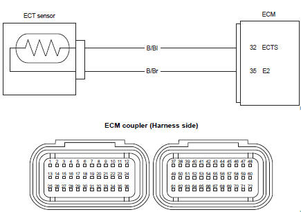
Wiring diagram
Troubleshooting
| Caution when using the multi-circuit tester, do not strongly touch the terminal of the ecm coupler with a needle pointed tester probe to prevent terminal damage. |
| Note after repairing the trouble, clear the dtc using sds tool. Refer to “use of sds diagnosis reset procedures” . |
C15 (use of mode select switch)
|
Step |
Action |
Yes |
No |
|
1 |
Special tool Tester knob indication
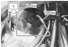
voltage ( Ect sensor input voltage 4.5 – 5.5 V ((+) terminal: b/bl – (–) terminal: ground, (+) terminal: b/bl – (–) terminal: b/br)
Is the voltage ok? |
Go to step 2. |
|
 (a): 09900–25008 (multi
 )
)
P0115-h (use of sds)
|
Step |
Action |
Yes |
No |
|
1 |
Special tool Tester knob indication
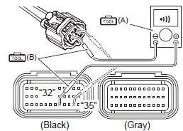
continuity test ( Ecm couplers (harness side)
Is the continuity ok? |
Go to step 2. | B/bl or b/br wire open. |
 )
)
P0115-l (use of sds)
|
Step |
Action |
Yes |
No |
|
|
1 |
Special tool Tester knob indication
continuity test (
Special tool Tester knob indication
voltage ( Ect sensor output voltage 0.15 – 4.85 V ((+) terminal: b/bl – (–) terminal: ground)
Are the continuity and voltage ok? |
Go to step 2. |
|
|
|
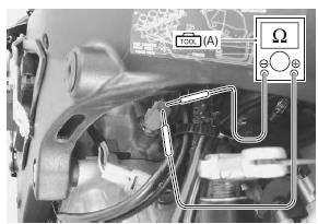
2 |
Special tool Tester knob indication resistance (Ω) Ect sensor resistance approx. 2.45 KΩ at 20 °c (68 °f) (terminal – terminal)
Is the resistance ok? |
|
Replace the ect
sensor with a new one. Refer to “ect sensor removal and installation” in section 1c . |
 (a): 09900–25008 (multi
 )
)
 )
)
 DTC “c14” (p0120-h/l): tp sensor circuit
malfunction
DTC “c14” (p0120-h/l): tp sensor circuit
malfunction
Detected condition and possible cause
Detected condition
Possible cause
C14
Output voltage is not within the following
range.
Difference between actual throttle op ...
 DTC “c21” (p0110-h/l): iat sensor circuit
malfunction
DTC “c21” (p0110-h/l): iat sensor circuit
malfunction
Detected condition and possible cause
Detected condition
Possible cause
C21
Output voltage is not with in the following
range.
0.15 V ≤ Sensor voltage < ...
Other materials:
Steering tension adjustment
Check the steering movement in the following
procedures:
by supporting the motorcycle with a jack, lift the front
wheel unit is off the floor 20 – 30 mm (0.8 – 1.2 In).
Remove the steering damper. Refer to “steering damper construction” .
Check to make sure that the cabl ...
Air valve removal and installation
Removal
Remove the wheel assembly. Refer to “front wheel assembly removal and
installation” and “rear wheel assembly removal and installation” .
Remove the tire. Refer to “tire removal and installation” .
Remove the air valve (1) from the wheel.
Installation
Install th ...