Suzuki GSX-R 1000 Service Manual: DTC “c14” (p0120-h/l): tp sensor circuit malfunction
Detected condition and possible cause
|
Detected condition |
Possible cause |
||
| C14 | Output voltage is not within the following
range. Difference between actual throttle opening and opening calculated by ecm is larger than specified value. 0.2 V ≤ Sensor voltage < 4.8 V |
|
|
| P0120 | H | Sensor voltage is higher than specified value. |
|
| L | Sensor voltage is lower than specified value. | ||
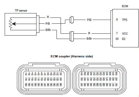
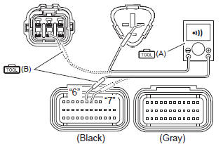
Wiring diagram
Troubleshooting
| Caution when using the multi-circuit tester, do not strongly touch the terminal of the ecm coupler with a needle pointed tester probe to prevent terminal damage. |
| Note after repairing the trouble, clear the dtc using sds tool. Refer to “use of sds diagnosis reset procedures” . |
C14 (use of mode select switch)
|
Step |
Action |
Yes |
No |
| 1 |
Special tool
Tester knob indication
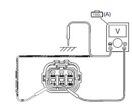
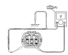
voltage ( Tp sensor input voltage 4.5 – 5.5 V ((+) terminal: r – (–) terminal: ground, (+) terminal: r – (–) terminal: b/br)
Is the voltage ok? |
Go to step 3. |
|
 (a): 09900–25008 (multi
 )
)
P0120-h (use of sds)
|
Step |
Action |
Yes |
No |
|
1 |
Special tool Tester knob indication
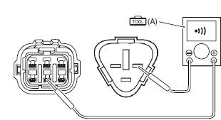
continuity (
Special tool Tester knob indication continuity test ( ) Ecm couplers (harness side)
Is the continuity ok? |
Go to step 3. | P/b wire shorted to vcc, or b/br wire open |
 (a): 09900–25008 (multi
 )
)
P0120-l (use of sds)
|
Step |
Action |
Yes |
No |
|
1 |
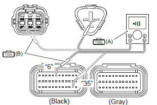
Special tool Tester knob indication
continuity test (
Special tool Tester knob indication
continuity test ( Ecm couplers (harness side)
Is the continuity ok? |
Go to step 2. | R or p/b wire open, or y/w wire shorted to ground. |
|
2 |
Special tool Tester knob indication
voltage ( Tp sensor input voltage 4.5 – 5.5 V ((+) terminal: r – (–) terminal: ground, (+) terminal: r – (–) terminal: b/br)
Is the voltage ok? |
Go to step 3. | Open or short circuit in the r or b/br wire. |
|
3 |
Special tool Tester knob indication
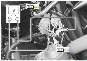
voltage ( Tp sensor output voltage throttle valve is closed: approx. 1.1 V throttle valve is opened: approx. 4.4 V ((+) terminal: p/b – (–) terminal: b/br)
Is the voltage ok? |
|
If check result is not
satisfactory, replace tp
sensor with a new one. Refer to “throttle body disassembly and assembly” in section 1d . |
 )
)
 )
)
 DTC “c13” (p0105-h/l): iap sensor circuit
malfunction
DTC “c13” (p0105-h/l): iap sensor circuit
malfunction
Detected condition and possible cause
Detected condition
Possible cause
C13
Iap sensor voltage is not within the
following range.
0.5 V ≤ Sensor voltage &l ...
 DTC “c15” (p0115-h/l): ect sensor circuit
malfunction
DTC “c15” (p0115-h/l): ect sensor circuit
malfunction
Detected condition and possible cause
Detected condition
Possible cause
C15
Output voltage is not with in the following
range.
0.15 V ≤ Sensor voltage < ...
Other materials:
Engine top side disassembly
It is unnecessary to remove the engine assembly from
the frame when servicing the cylinder head cover and
camshafts.
Note
before servicing the engine top side
components (until camshafts removal) with
the engine in place, remove the following
parts:
air cleaner box
...
Ckp sensor inspection
Refer to “electrical components location” in section 0a .
Ckp sensor peak voltage
Lift and support the fuel tank. Refer to “fuel tank
removal and installation” in section 1g (page 1g-
9).
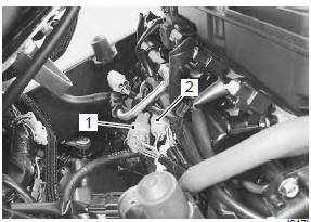
Disconnect the ckp sensor coupler (1).
Note
be sure that all of the couplers are connect ...
Cushion lever removal and installation
Removal
Remove the right side cowling and side frame covers. Refer to “exterior
parts removal and installation” in section 9d .
Support the motorcycle with a jack to relieve load on
the cushion levers.
Remove the left muffler and muffler chamber heat guard no. 2. Refer to
...