Suzuki GSX-R 1000 Service Manual: DTC “c13” (p0105-h/l): iap sensor circuit
malfunction
Detected condition and possible cause
|
Detected condition |
Possible cause |
| C13 |
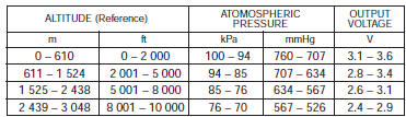
Iap sensor voltage is not within the
following range.
0.5 V ≤ Sensor voltage < 4.85 V
| Note
note that atmospheric pressure
varies depending on weather
conditions as well as altitude.
Take that into consideration
when inspecting voltage. |
|
- Clogged vacuum passage between throttle body and
iap sensor.
- Air being drawn from vacuum passage between throttle
body and iap sensor.
- Iap sensor circuit open or shorted to ground.
- Iap sensor malfunction.
- Ecm malfunction.
|
| P0105 |
H |
Sensor voltage is higher than specified
value |
- Iap sensor circuit is open or shorted to vcc or ground
circuit open.
- Iap sensor circuit is shorted to ground or vcc circuit
open.
|
| L |
Sensor voltage is lower than specified
value. |
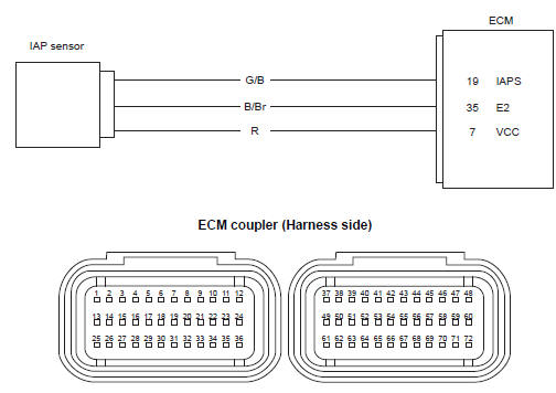
Wiring diagram
Troubleshooting
| Caution
when using the multi-circuit tester, do not strongly touch the terminal
of the ecm coupler with a
needle pointed tester probe to prevent terminal damage. |
| Note
after repairing the trouble, clear the dtc using sds tool. Refer to “use
of sds diagnosis reset procedures” . |
C13 (use of mode select switch)
|
Step |
Action |
Yes |
No |
| 1 |
- Turn the ignition switch off.
- Lift and support the fuel tank. Refer to “fuel tank removal and
installation” in section 1g .
- Check the iap sensor coupler (1) for loose or poor
contacts.
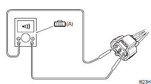
If ok, then measure the iap sensor input voltage.
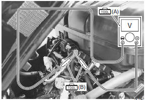
- Disconnect the iap sensor coupler.
- Turn the ignition switch on.
- Measure the input voltage between the r wire and
ground.
If ok, then measure the voltage between the r wire and
b/br wire.
Special tool
 (a): 09900–25008 (multi (a): 09900–25008 (multi
circuit tester set)
Tester knob indication
voltage ( ) )
Iap sensor input voltage
4.5 – 5.5 V
((+) terminal: r – (–) terminal: ground, (+) terminal: r
– (–) terminal: b/br)
Is the voltage ok? |
Go to step 3. |
- Loose or poor
contacts on the ecm
coupler.
- Open or short circuit
in the r or b/br wire.
|
P0105-h for iap sensor (use of sds)
|
Step |
Action |
Yes |
No |
| 1 |
- Turn the ignition switch off.
- Lift and support the fuel tank. Refer to “fuel tank removal and
installation” in section 1g .
- Check the iap sensor coupler (1) for loose or poor
contacts.
If ok, then check the iap sensor lead wire continuity.
- Disconnect the iap sensor coupler.
- Check the continuity between the r wire and g/b wire.
If the sound is not heard from the tester, the circuit
condition is ok.
Special tool
 (a): 09900–25008 (multi (a): 09900–25008 (multi
circuit tester set)
Tester knob indication
continuity ( ) )
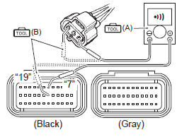
- Disconnect the ecm couplers. Refer to “ecm removal and
installation” in section 1c .
- Insert the needle pointed probes to the lead wire coupler
- Check the continuity between the g/b wire and terminal
“19”.
If ok, then check the continuity between the b/br wire
and terminal “35”.
Special tool
(a): 09900–25008 (multi
circuit tester set)
(b): 09900–25009
(needle-point probe set)
Tester knob indication
continuity test ( )
Ecm couplers (harness side)
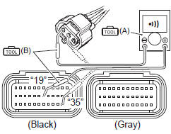
Is the continuity ok? |
Go to step 3. |
G/b wire shorted to
vcc, or b/br wire open. |
P0105-l for iap sensor (use of sds)
|
Step |
Action |
Yes |
No |
| 1 |
- Turn the ignition switch off.
- Lift and support the fuel tank. Refer to “fuel tank removal and
installation” in section 1g .
- Check the iap sensor coupler (1) for loose or poor
contacts.
If ok, then check the iap sensor lead wire continuity.
- Disconnect the iap sensor coupler.
- Check the continuity between the g/b wire and ground.
Also, check the continuity between the g/b wire and b/
br wire. If the sound is not heard from the tester, the
circuit condition is ok.
Special tool
 (a): 09900–25008 (multi (a): 09900–25008 (multi
circuit tester set)
Tester knob indication
continuity ( ) )
- Disconnect the ecm couplers. Refer to “ecm removal and
installation” in section 1c .
- Insert the needle pointed probes to the lead wire coupler
- Check the continuity between the r wire and terminal
“7”. Also, check the continuity between the g/b wire and
terminal “19”.
Special tool
 (a): 09900–25008 (multi (a): 09900–25008 (multi
circuit tester set)
 (b): 09900–25009 (b): 09900–25009
(needle-point probe set)
Tester knob indication
continuity ( ) )
Ecm couplers (harness side)
Is the continuity ok? |
Go to step 2. |
R and g/b wire open, g/
b wire shorted to
ground. |
| 2 |
- Connect the ecm couplers.
- Turn the ignition switch on.
- Measure the input voltage between the r wire and
ground.
If ok, then measure the voltage between the r wire and
b/br wire
Special tool
 (a): 09900–25008 (multi (a): 09900–25008 (multi
circuit tester set)
Tester knob indication
voltage ( ) )
Iap sensor input voltage
4.5 – 5.5 V
((+) terminal: r – (–) terminal: ground, (+) terminal: r
– (–) terminal: b/br)
Is the voltage ok? |
Go to step 3. |
- Loose or poor
contacts on the ecm
coupler.
- Open or short circuit
in the r or b/br wire.
|
| 3 |
- Turn the ignition switch off.
- Connect the ecm couplers and iap sensor coupler.
- Insert the needle pointed probes to the lead wire coupler.
- Run the engine at idle speed and measure the iap
sensor output voltage between the g/b wire and b/br
wire.
Special tool
(a): 09900–25008 (multi
circuit tester set)
(b): 09900–25009
(needle-point probe set)
Tester knob indication
voltage ( )
Iap sensor output voltage
approx. 2.7 V at idle speed
((+) terminal: g/b – (–) terminal: b/br)
Is the voltage ok? |
Go to step 4. |
- Check the vacuum
hose for crack or
damage.
- Open or short circuit
in the g/b wire.
- If vacuum hose and wire are ok, replace the iap sensor with a
new one. Refer to “iap sensor removal and installation” in section
1c .
|
| 4 |
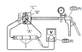
- Turn the ignition switch off.
- Remove the iap sensor. Refer to “iap sensor removal and
installation” in section 1c .
- Connect the vacuum pump gauge to the vacuum port of
the iap sensor.
- Arrange 3 new 1.5 V batteries (1) in series (check that
total voltage is 4.5 – 5.0 V) and connect (–) terminal to
the ground terminal “b” and (+) terminal to the vcc
terminal “a”.
- Check the voltage between vout terminal “c” and
ground. Also, check if voltage reduces when vacuum is
applied by using vacuum pump gauge.
Special tool
 (a): 09917–47011 (vacuum (a): 09917–47011 (vacuum
pump gauge set)
 (b): 09900–25008 (multi (b): 09900–25008 (multi
circuit tester set)
Tester knob indication
voltage ( ) )
Is the voltage ok? |
- G/b, r or b/br wire
open or shorted to
ground, or poor “19”,
“7” or “35”
connection.
- If wire and
connection are ok,
intermittent trouble or
faulty ecm.
- Recheck each
terminal and wire
harness for open
circuit and poor
connection.
- Replace the ecm with a known good one, and inspect it again.
Refer to “ecm removal and installation” in section 1c .
|
If check result is not satisfactory, replace the iap sensor with a
new one. Refer to “iap sensor removal and installation” in section 1c . |
Detected condition and possible cause
Detected condition
Possible cause
The signal does not reach ecm for 3 sec. Or more, after
receiving the starter signal.
...
Detected condition and possible cause
Detected condition
Possible cause
C14
Output voltage is not within the following
range.
Difference between actual throttle op ...
Other materials:
Ecm / various sensors
Since each component is a high-precision part, great
care should be taken not to apply any severe impacts
during removal and installation.
Be careful not to touch the electrical terminals of the
electronic parts (ecm, etc.). The static electricity from
your body may damage them. ...
Isc valve reset
When removing or replacing the throttle body assembly,
reset the isc valve learned value in the following
procedures:
turn the ignition switch on position.
Set up the sds tools. (Refer to the sds operation
manual for further details.)
Click “active control”.
Click “is ...
Throtile cable play
This motorcycle has a twin throttle
cable system. Cable A is for pulling
cable and cable B is for
returning.
To adjust the cable play:
Loosen the lock nut 1.
Turn the adjuster 2 so that the
throttle grip has 2.0 - 4.0 Mm
(0.08- 0.16 In) play.Tighten the lock nut 1.
...
 DTC “c12” (p0335): ckp sensor circuit
malfunction.
DTC “c12” (p0335): ckp sensor circuit
malfunction. DTC “c14” (p0120-h/l): tp sensor circuit
malfunction
DTC “c14” (p0120-h/l): tp sensor circuit
malfunction